
PRINTED 0709 316437-001
On-Demand Gas Tankless
Water Heater Service Manual
Service information for single and multiple unit installations
for residential, commercial, recirculation and storage tank systems.
ATI-305-N GTS-305-NI GT-305-NI
ATI-305-P GTS-305-PI GT-305-PI
ATO-305-N GTS-305-NE GT-305-NE
ATO-305-P GTS-305-PE GT-305-PE
ATI-505-N GTS-505-NI GT-505-NI
ATI-505-P GTS-505-PI GT-505-PI
ATO-505-N GTS-505-NE GT-505-NE
ATO-505-P GTS-505-PE GT-505-PE
ATI-705-N GTS-705-NI GT-705-NI
ATI-705-P GTS-705-PI GT-705-PI
ATO-705-N GTS-705-NE GT-705-NE
ATO-705-P GTS-705-PE GT-705-PE
ATI-705A-N GTS-705-NIA AGT-705-NI
ATI-705A-P GTS-705-PIA AGT-705-PI
ATO-705A-N GTS-705-NEA AGT-705-NE
ATO-705A-P GTS-705-PEA AGT-705-PE
Series 100/101 & Series 200/201

Table of Contents
General Information................................................3-5
Specifications.........................................................6, 7
Schematic Diagrams..............................................8, 9
Fault Isolation..................................................... 10-12
Electrical Diagnostic Points
305e/o, 305i, 505e/o 505i ................................13, 14
705e/o (ASME), 705i (ASME) .........................15, 16
Wire Diagrams
305e/o, 305i, 505e/o, 505i .....................................17
705e/o (ASME), 705i (ASME) ...............................18
Flushing the Heat Exchanger .................................19
Component Replacement Instructions
Gas Control Assembly
305e/o, 305i, 505e/o, 505i ...............................20, 21
705e/o (ASME), 705i (ASME) ..........................22, 23
Fan
505e/o, 305e/o.......................................................24
305i, 505i ...............................................................25
705e/o (ASME), 705i (ASME) ...............................26
PC Board
305e/o, 305i, 505e, 505i ................................. 27, 28
705e/o (ASME ), 705i (ASME) ............................. 29
Water Flow Control Assembly
305e, 305i, 505e, 505i .................................... 30, 31
505e, 505i ....................................................... 32, 33
705e/o (ASME), 705i (ASME) .............................. 34
Heat Exchanger
305e ................................................................. 35-37
505e /o.............................................................. 38-40
305i .................................................................. 41-44
505i .................................................................. 45-49
705e/o (ASME)................................................. 50-51
705i (ASME) .................................................... 52-54
Gas Pressure Setting Procedure..................... 55, 56
Manifold Pressure Settings.................................... 57
Dip Switches............................................................ 58
On-Demand Gas Tankless Water Heater Service Manual
2
Key to Trade Names in this Manual:
(ASME) Indicates that the ASME
models are included.
(N) Indicates Natural Gas.
(P) Indicates Propane Gas.
(e) Indicates Outdoor Models.
(i) Indicates Indoor Models.
(o) Indicates Outdoor Models.

General Information
Safety Definitions
This is the safety alert symbol. This symbol alerts you to potential hazards that can kill or hurt you and
others.
Indicates an imminently hazardous situation which, if not avoided, will result in death or
serious injury.
Indicates a potentially hazardous situation which, if not avoided, could result in death or
serious injury.
Indicates a potentially hazardous situation which, if not avoided, could result in minor or
moderate injury. It may also be used to alert against unsafe practices.
DANGER
CAUTION
WARNING
Recommended Tools
• Volt/Ohm/Amp meter with test probes
• Digital manometer or U tube type manometer with 14 inch water column (W.C.) scale, a hose and two 1/8 inch
taps
• assorted wrenches including a 3/16 Allen wrench
• assorted screw drivers including a long shafted, magnetic tipped screw driver
• leak solution or leak detector
• Teflon tape
Using this Manual
Repairs should be performed by a qualified service technician.
The following information can be referenced for additional information.
• Operation and Installation Manual
• Hot Water System Design Manual
• Technical Sheets
• Technical Bulletins
Technical Support
Visit the brand website for additional support including contact information for our Technical Service Department.
WARNING
There are a number of live tests that are required when fault finding this product. Extreme care should be used at
all times to avoid contact with energized components inside the water heater. Before checking for resistance
readings disconnect the power source to the unit and isolate the item from the circuit (unplug it).
If any of the original wire as supplied with the appliance must
be replaced, it must be replaced with type 18 AWG wire or its
equivalent.
Label all wires prior to disconnection when
servicing controls. Wiring errors can cause
improper and dangerous operation.
CAUTION
On-Demand Gas Tankless Water Heater Service Manual
3

General Information
On-Demand Gas Tankless Water Heater Service Manual
4
Service Information
The on-demand water heaters must be installed according to all local and state codes or, in the absence
of local and state codes, the “National Fuel Gas Code”, ANSI Z223.1 (NFPA 54) - current edition.
CSA American, Inc. National Fire Protection Association
8501 East Pleasat Valley Road 1 Batterymarch Park
Cleveland, OH 44131 Quincy, MA 02269
Check your phone listings for the local authorities having jurisdiction over your installation.
Massachusetts code requires this water heater to be installed in accordance with Massachusetts Plumbing
and Fuel Gas Code 248 CMR Section 2.00 and 5.00.
Water Temperature Regulation
For systems with storage tanks, the water
temperature in certain situation may vary up
to 30°F (16.7°C) higher or lower at the point
of use such as, bathtubs,showers, sink, etc.
HOTTER WATER CAN SCALD: Water heat-
ers, are intended to produce hot water. Water
heated to a temperature which will satisfy
space heating, clothes washing, dish wash-
ing, and other sanitizing needs can scald and
permanently injure you upon contact. Some
people are more likely to be permanently in-
jured by hot water than others. These include
the elderly, children, the infirm, or physically/
mentally handicapped. If anyone using hot
water in the home fits into one of these
groups or if there is a local code or state law
requiring a certain temperature water at the
hot water tap, then you must take special
precautions.
Water temperature over 125°F can cause
severe burns instantly or death from scalds.
Children, disabled and elderly are at highest
risk of being scalded.
Feel water before bathing or showering.
Temperature limiting valves are available.
WARNING
Temperature
Settings
Time to Produce 2nd & 3rd
Degree Burns on Adult Skin
160°F (71°C)
About 1/2 second
150°F (66°C) About 1-1/2 seconds
140°F (60°C) Less than 5 seconds
130°F (54°C) About 30 seconds
120°F (49°C) More than 5 minutes
80°F (27°C) - - - - - - - - - - - - - - - -
Table “A”
NOTE: This water heater must be installed according to all local and state codes or, in the absence
of local and state codes, the “National Fuel Gas Code”, ANSI Z223.1(NFPA 54)-current edition.
In addition to using the lowest possible temperature setting that satisfies your hot water needs, a means
such as a mixing valve, should be used at hot water taps used by these people or at the water heater.
Mixing valves are available at plumbing supply or hardware stores. Follow manufacturer’s instructions for
installation of the valves. Before changing the factory setting on the thermostat see Table “A”. Using the
lowest hot water temperature that meets your needs will also provide the most energy efficient operation
of the water heater.
Never allow small children to use a hot water
tap, or to draw their own bath water. Never
leave a child or handicapped person un-
attended in a bathtub or shower.
NOTE: A water temperature range of 120
°F -
140
°F (49°C-60°C) is recommended by most
dishwasher manufacturers.

General Information
On-Demand Gas Tankless Water Heater Service Manual
5
Closed System/Thermal Expansion
CAUTION - PROPERTY DAMAGE HAZARD
As water is heated, it expands (thermal expan-
sion). In a closed system, the volume of water
will grow. As the volume of water grows, there
will be a corresponding increase in water pres-
sure due to thermal expansion. Thermal expan-
sion can cause premature tank failure (leakage).
This type of failure is not covered under the
limited warranty. Thermal expansion can also
cause intermittent temperature-pressure relief
valve operation: water discharged from the valve
due to excessive pressure build up. The temper-
ature / pressure relief valve is not intended for
the constant relief of thermal expansion. This
condition is not covered under the limited war-
ranty.
A properly-sized thermal expansion tank should
be installed on all closed systems to control the
harmful effects of thermal expansion. Contact a
local plumbing service agency to have a thermal
expansion tank installed.
Hot Water
Outlet
In a closed system use a
thermal expansion tank
Cold Water
Inlet Valve
Pressure Reducing
Valve with Bypass
Main Water
Supply
Cold Water Supply
to Fixture
Temperature and
Pressure Relief Valve
Discharge line
6” Max. above drain
Drain line 3/4”
ID Min.
Drain
1“ Min.
Metal Drain
Pan 1-3/4”
Depth Max.
Massachusetts:
Install a vacuum relief
in cold water line per
section 19 MGL 142
Figure 1a
Typical water piping installation
Storage
Tank
Hot Water Return Line
Explosion Hazard
If the temperature and pressure relief valve
is dripping or leaking, have a qualified
service technician replace it.
Examples of a qualified service technician
include: Licensed plumbers, authorized gas
company personnel, and authorized service
personnel.
Do not plug valve.
Do not remove valve.
Failure to follow these instructions can
result in death, or explosion.
WARNING
Temperature and Pressure
Relief Valve
For protection against excessive pressures and
temperatures, a temperature and pressure relief
valve must be installed in the opening on the
on-demand storage tank. This valve must be
design certified by a nationally recognized testing
laboratory that maintains periodic inspection of
the production of listed equipment or materials
as meeting the requirements for Releif Valves for
Hot Water Supply Systems, ANSI Z21.22. The
function of the temperature and pressure relief
valve is to discharge water in large quantities in
the event of excessive temperature or pressure
developing in the water heater. The valve’s relief
pressure must not exceed the working pressure
the water heater as stated on the data plate.
IMPORTANT: Only a new temperature and
pressure relief valve should be used with your
water heater.Do not use an old or existing valve
as it may be damaged or not adequate for the
working pressure of the new water heater.
Do not place any valve between the relief valve
and the tank.

Specifications
Model Number
Temperature Range
305
15,000 - 199,000 NG
15,000 - 190,000 LP
705/705 ASME
Indoor (i)
On-Demand Gas Tankless Water Heater Service Manual
6
Input
Min. - Max.
(BTU)
Flow Rate
Hot water capacity
@ 45°F Temp. Rise
0.6 - 5.3 GPM
(2.3 - 20.1 LPM)
5.3 GPM (20.1 LPM)
Efficiency
Rating
84%
505
15,000 - 199,000 NG
15,000 - 190,000 LP
0.6 - 8.5 GPM
(2.3 - 32.0 LPM)
7.4 GPM (28 LPM) NG
7.1 GPM (27 LPM) LP
98 -140° F (37 - 60° C) [1]
84%
98 -140° F (37 - 60° C) [2]
98 -140° F (37 - 60° C) [2]
84%
8.8 GPM (33.3 LPM)
19,000 - 237,000
NG & LP
0.6 - 9.8 GPM
(2.3 - 37 LPM)
Model Number
Temperature Range
305
15,000 - 199,000
NG & LP
705/705 ASME
Outdoor (e/o)
Input
Min. - Max.
(BTU)
Flow Rate
Hot water capacity
@ 45°F Temp. Rise
0.6 - 5.3 GPM
(2.3 - 20.1 LPM)
5.3 GPM (20.1 LPM)
Efficiency
Rating
83%
505
0.6 - 8.5 GPM
(2.3 - 32.0 LPM)
7.3 GPM (27.6 LPM)
98 -140° F (37 - 60° C) [1]
83%
98 -140° F (37 - 60° C) [2]
98 -140° F (37 - 60° C) [2]
83%
8.7 GPM (32.9 LPM)
19,000 - 237,000
NG & LP
0.6 - 9.8 GPM
(2.3 - 37 LPM)
15,000 - 199,000
NG & LP
Residential Series
100/101*
NOTE:
[1] Minimum activation flow is approximately 0.6 gallons/minute (2.3 liters/min). Max temperature is 160° (71° C)
with the commercial controller for commercial and hydronic applications only.
[2] Max temperature is 185 ºF (85 ºC) with the commercial controller for commercial and hydronic applications only.
*100 Series is Natural Gas
*101 Series is Propane Gas
Specifications
Model Number
Temperature Range
305
Indoor (i)
On-Demand Gas Tankless Water Heater Service Manual
7
Input
Min. - Max.
(BTU)
Flow Rate
Hot water capacity
@ 45°F Temp. Rise
0.6 - 7.5 GPM
(2.3 - 28.4 LPM)
Efficiency
Rating
84%
505
15,000 - 199,000 NG
15,000 - 190,000 LP
0.6 - 9.4 GPM
(2.3 - 35.5 LPM)
98 -140° F (37 - 60° C) [1]
84%
98 -140° F (37 - 60° C) [2]
Model Number
Temperature Range
305
15,000 - 180,000
NG & LP
Outdoor (e/o)
Input
Min. - Max.
(BTU)
Flow Rate
Hot water capacity
@ 45°F Temp. Rise
0.6 - 7.5 GPM
(2.3 - 28.4 LPM)
6.6 GPM (25.0 LPM)
Efficiency
Rating
83%
505
0.6 - 9.4 GPM
(2.3 - 35.5 LPM)
7.4 GPM (28.0 LPM)
98 -140° F (37 - 60° C) [1]
83%
98 -140° F (37 - 60° C) [2]
15,000 - 199,000
NG & LP
Residential Series
200/201*
NOTE:
[1] Minimum activation flow is approximately 0.6 gallons/minute (2.3 liters/min). Max temperature is 160° (71° C)
with the commercial controller for commercial and hydronic applications only.
[2] Max temperature is 185 ºF (85 ºC) with the commercial controller for commercial and hydronic applications only.
6.6 GPM (25.0 LPM)
7.4 GPM (28.0 LPM) NG
15,000 - 180,000
NG & LP
7.1 GPM (26.9 LPM) LP
*200 Series is Natural Gas
*201 Series is Propane Gas
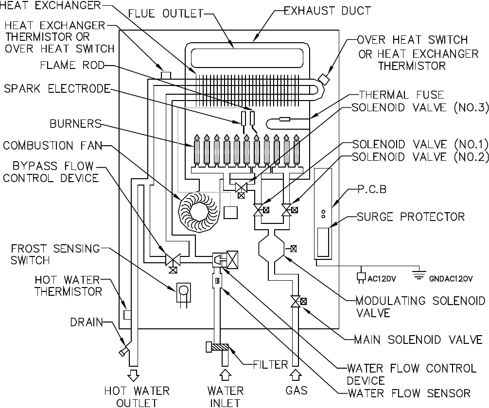
Schematic Diagrams
Outdoor Model
(NOT PRESENT ON
ALL MODELS)
(LOCATED ON BRACKET NEAR
FAN ON SOME MODELS)
(NOT PRESENT ON
ALL MODELS)
On-Demand Gas Tankless Water Heater Service Manual
8
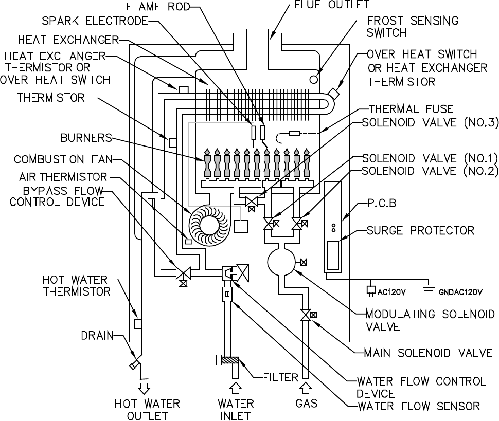
Schematic Diagrams
Indoor Model
(NOT PRESENT ON
ALL MODELS)
(NOT PRESENT ON
ALL MODELS)
(LOCATED ON BRACKET NEAR
FAN ON SOME MODELS)
On-Demand Gas Tankless Water Heater Service Manual
9
Fault Isolation
Some of the checks below may need to be done by a qualified service technician. Call a
service technician for any remedy that involves gas or electricity. Call a service
technician if you have any doubt or reservation about performing the remedy yourself.
WARNING
Accessing Operating Information
To display the most recent error codes press and hold the “On/Off” button for 2 seconds. While holding the “On/
Off” button press the ▲ button. The last 9 error codes will flash one after the other. To exit this mode press the
“On/Off” and ▲ button as before.
To display the water flow through the water heater press and hold the ▲ button for 2 seconds and without
releasing the ▲ button press the “On/Off” button.
To display the outlet water temperature press and hold the ▼ button for 2 seconds and without releasing the ▼
button press the “On/Off” button.
Standard and Commercial Controllers
1. Water Flow Begins.
• Water Flow Sensor sends pulses to the PC
Board.
• PC Board senses flow greater than 0.6 GPM
(approximate).
• Firing Sequence begins.
2. Firing Sequence.
• PC Board monitors inlet/outlet water
temperature, temperature set point, and water
flow rate.
• Combustion fan energized. Purges combustion
chamber.
• Spark igniter begins sparking.
• Gas control valve opens to minimum fire rate.
• Flame rod proves ignition.
• Spark igniter stops sparking.
3. Normal Operation.
• PC Board monitors flame rod, fan motor
frequency, outlet water temperature, controller
temperature set point and water flow rate.
• Gas control valve modulates gas input to
required firing rate.
• Combustion fan speed is adjusted for the
required firing rate.
• Water flow control valve is adjusted as needed.
4. Shut-down Sequence.
• PC Board senses flow rate less than 0.5 gpm
(approximate).
• Gas control valve closes.
• Water flow control valve resets to standby
position.
• Combustion fan runs for a short period of time
at low speed.
5. Standby Mode.
• PC Board monitors water temperature and
remote controls.
• Freeze protection is activated as needed.
Operation
On-Demand Gas Tankless Water Heater Service Manual
10
The On-Demand water heater has the ability to check its own operation continuously. If a fault occurs, an error
code will flash on the display of the remote controller. This assists with diagnosing the fault and may enable
you to overcome a problem without a service call.

Fault Isolation
Code Fault Remedy
02
No burner operation during
freeze protection mode
Service Call - Check for possible freeze damage to heat exchanger.
10
Air Supply or Exhaust
Blockage
Ensure approved venting materials are being used.
Check that nothing is blocking the flue inlet or exhaust.
Check all vent components for proper connections.
Ensure vent length is within limits.
Ensure condensation collar was installed correctly.
Verify dip switches are set properly.
Check fan for blockage.
11
No Ignition Check that the gas is turned on at the water heater, gas meter, or cylinder.
Ensure gas type and pressure is correct.
Ensure gas line, meter, and/or regulator is sized properly.
Bleed all air from gas lines.
Verify dip s
witches are set properly.
Ensure appliance is properly grounded.
Disconnect 2-Unit or Multi-Unit connections to isolate the problem.
Ensure igniter is operational.
Check igniter wiring harness for damage.
Check gas solenoid valves for open or short circuits.
Remove burner cover and ensure all burners are properly seated.
Remove burner plate and inspect burner surface for condensation or debris.
12
Flame Failure Check that the gas is turned on at the water heater and gas meter. Check for
obstructions in the flue outlet.
Ensure gas line, meter, and/or regulator is sized properly.
Ensure gas type and pressure is correct.
Bleed all air from gas lines.
Ensure proper venting material was installed.
Ensure condensation collar was installed properly.
Ensure vent length is within limits.
Verify dip switches are set properly.
Ensure appliance is properly grounded.
Disconnect keypad.
Disconnect all 2-Unit or Multi-Unit connections to isolate the problem.
Check power supply for loose connections.
Check power supply for proper voltage and voltage drops.
Ensure flame rod wire is connected.
Remove flame rod and check for carbon build-up; clean with sand paper or emery
cloth.
Disconnect and reconnect all wiring harnesses on unit and PC board.
Check all components for electrical short.
Check gas solenoid valves for open or short circuits.
Remove burner plate and inspect burner surface for condensation or debris.
On-Demand Gas Tankless Water Heater Service Manual
11

14
Thermal Fuse Check gas type of unit and ensure it matches gas type being used.
Check for restrictions in air flow around unit and vent terminal.
Check for low water flow in a circulating system causing short-cycling.
Ensure dip switches are set to the proper position.
Check for foreign materials in combustion chamber and/or exhaust piping.
Check heat exchanger for cracks and/or separations.
Check heat exchanger surface for hot spots which indicate blockage due to scale build-
up. Refer to instructions in manual for flushing heat exchanger.
Measure resistance of safety circuit.
Ensure high fire and low fire manifold pressure is correct.
Check for improper conversion of product.
16
Over Temperature
Warning
Check for restrictions in air flow around unit and vent terminal.
Check for low water flow in a circulating system causing short-cycling.
Check for foreign materials in combustion chamber and/or exhaust piping.
Check for clogged heat exchanger.
32
Outgoing Water
Temperature Sensor
Fault
Check sensor wiring for damage.
Measure resistance of sensor.
Clean sensor of scale build-up.
Replace sensor.
33
Heat Exchanger
Outgoing Temperature
Sensor Fault
Check sensor wiring for damage.
Measure resistance of sensor.
Clean sensor of scale build-up.
Replace sensor.
34
Combustion Air
Temperature Sensor
F
ault
Check for restrictions in air flow around unit and vent terminal.
Check sensor wiring for damage.
Measure resistance of sensor.
Clean sensor of scale build-up.
Ensure fan blade is tight on motor shaft and is in good condition.
Replace sensor.
52
Modulating Solenoid
Valve Signal Abnormal
Check modulating gas solenoid valve wiring harness for loose or damaged terminals.
Measure resistance of valve coil.
61
Combustion Fan
Failure
Ensure fan will turn freely.
Check wiring harness to motor for damaged and/or loose connections.
Measure resistance of motor winding.
65
Water Flow Control
Fault
The water flow control valve has failed to close during the bath fill function. Immediately
turn off the water and discontinue the bath fill function. Contact a state qualified or
licensed contractor to service the appliance.
71
SV0, SV1, SV2, and
SV3 Solenoid Valve
Circuit Fault
Check wiring harness to all solenoids for damage and/or loose connections.
Measure resistance of each solenoid valve coil.
72
Flame Sensing Device
Fault
Ensure flame rod is touching flame when unit fires.
Check all wiring to flame rod for damage.
Remove flame rod and check for carbon build-up; clean with sand paper or emery cloth.
Check inside burner chamber for any foreign material blocking flame at flame rod.
Measure micro amp output of sensor circuit with flame present.
Replace flame rod.
LC
Scale Build-up in Heat
Exchanger (when
checking maintenance
code history, “00” is
substituted for “LC”)
Flush heat exchanger. Refer to instructions in manual.
Replace heat exchanger.
NOTE: The LC code is the only code that will allow the unit to keep running. The
display will alternate between the LC code and the temperature setting. The controller
will continue to beep. The LC code will reset if power is turned off and then on.
No
code
Nothing happens when
water flow is activated.
Clean inlet water supply filter, see page 19 step 12 for cleaning instructions.
On new installations ensure hot and cold water
lines are not reversed.
Check for bleed over. Isolate unit from building by turning off hot water line to building.
Isolate the circulating system if present. Open your pressure relief valve; if water is
flowing, there is bleed over in your plumbing.
Ensure you have at least the minimum flow rate required to fire unit.
Ensure turbine spins freely.
Measure the resistance of the water flow control sensor.
Code Fault Remedy
Fault Isolation
On-Demand Gas Tankless Water Heater Service Manual
12

Electrical Diagnostic Points
Wire Color Voltage Resistance Connector No. Pin No.’s
(SV1, SV2, SV3, POV) Gas Valve and Modulating Solenoids
(Main) Pink - Black
11 - 13 VDC 36.8 - 44.8 ohms
H5 6 ~ 7
6 ~ 5 6H wolleY - kcalB )1VS(
6 ~ 4 7H eulB - kcalB )2VS(
6 ~ 3 8H nworB - kcalB )3VS(
(POV) Pink - Pink 2 - 15 VDC 67 - 81 ohms H3 9 ~ 10
(M) Water Flow Servo
Red - Blue 11 - 13 VDC 22 - 26 ohms F7 9 ~ 10
Gray - Brown 4 - 6 VDC N/A F7 5 ~ 7
Gray - Yellow N/A N/A F7 5 ~ 8
NOTE: At the F connector on the PCB: gray wire turns to black, orange wire turns to red
(QS) Water Flow Sensor
Black - Red 11 - 13 VDC 5.5 - 6.2 K ohms F2 1 ~ 3
Yellow - Black 4 - 7 VDC 1 -
1.4 mega ohms F2 2 ~ 3
Bypass Flow Control (only on 505e/o and 505i)
Brown - White
2 - 6 VDC
(unit in operating
mode)
15 - 35 K ohms G1
1 ~ 5
5 ~ 2 etihW - egnarO
5 ~ 3 etihW - wolleY
5 ~ 4 dnuorG/etihW - deR
(IG) Ignition System
Gray - Gray 90 - 110 VAC N/A C1 1 ~ 2
(FM) Combustion Fan Motor
Red - Black 6 - 45 VDC N/A E1 1 ~ 2
White - Black 5 - 10 VDC 9.2 - 9.4 K ohms E1 2 ~ 4
Yellow - Black 11 ~ 13 VDC 3.5 - 3.9 K ohms E1 2 ~ 3
With the meter set on hertz scale, 60-420 hertz should be across the red and yellow wires at
terminals 2 and 4.
On-Demand Gas Tankless Water Heater Service Manual
13
305e/o, 305i, 505e/o, 505i
Electrical Diagnostic Points
Wire Color Voltage Resistance Connector No. Pin No.’s
Thermal Fuse / Overheat Switch
Red - Red 11 - 13 VDC below 1 ohm F6 H1 F6 ~ H12
Flame Rod
Place one lead of the meter to the flame rod and the other to ground. With the unit running, 5-150
VAC should be read. Set the meter to the μ amp scale and series the meter in line with the flame
rod. Proper flame circuit should read 1 μ amp or greater. If not, then remove the flame rod and
check for carbon and damage.
Thermistors
Check all thermistors by inserting meter leads into each end of the thermistor plug. Set the meter to
the 20 K ohm scale and read resistance. Applying heat to the thermistor bulb should decrease the
resistance. Applying ice to the thermistor bulb should increase the resistance. Typical resistance
values are:
11.4-14 K ohm for 59°F; 6.4-7.8 K ohm for 86°F; 3.6-4.5 K ohm for 113°F; 2.2-2.7 K ohm
for 140°F; 0.6-0.8 K ohm for 221°F
Outgoing Water Thermistor
4 ~ 3 5F evoba ees etihW - etihW
Heat Exchanger Temperature Thermistor
11 ~ 3 4F evoba ees etihW - kniP
21 ~ 3 3F ev
oba ees etihW - egnarO
Surge Protector
Black - White 108 - 132 VAC N/A D2 1 ~ 3
Blue - Brown 108 - 132 VAC N/A D1 1 ~ 3
With the power off, check the continuity through the surge protector. Check by placing one meter
lead on the top pin #1 and bottom pin #3. Check by placing one meter lead on the top pin #3 and
bottom pin #1. If there is continuity across both sets of points, then the surge protector is good.
Controller
Terminals B1
10 - 13 VDC 1.5 - 3.0 K ohms B 1 ~ 3
Frost Protection
There are electrical heating elements mounted at different points to protect the water heater from
freezing.
heaters located on the hot water outlet line 180 - 207 ohms
heater located on heat exchanger piping 156 - 180 ohms
heater located on water flow sensor 24 - 28 ohms
Amp fuses
There are two inline 3 amp glass fuses. Remove the fuse and check continuity through it. If there is
continuity then the fuse is good.
Intake Air Thermistor
On-Demand Gas Tankless Water Heater Service Manual
14
305e/o, 305i, 505e/o, 505i
Electrical Diagnostic Points
Wire Color Voltage Resistance Connector No. Pin No.’s
(SV1, SV2, SV3, POV) Gas Valve and Modulating Solenoids
(Main) Pink - Black
11 - 13 VDC
24 - 28 ohms H3 6 ~ 7
6 ~ 5 4H deR - kcalB )1VS(
6 ~ 4 5H egnarO - kcalB )2VS(
6 ~ 3 6H wolleY - kcalB )3VS(
(POV) Orange - Orange 2 - 15 VDC 67 - 81 ohms H2 9 ~ 10
(M) Water Flow Servo
Red - Blue 11 - 13 VDC 22 - 28 ohms F5 9 ~ 10
Gray - Brown 4 - 6 VDC N/A F5 5 ~ 7
Gray - Yellow N/A N/A F5 5 ~ 8
NOTE: At the F connector on the PCB: gray wire turns to black
(QS) Water Flow Sensor
Black - Red 11 - 13 VDC 5.5 - 6.2 K ohms F2 1 ~ 3
Yellow - Black 4 - 7 VDC 1 - 1.4 mega ohms F
2 2 ~ 3
Bypass Flow Control
Brown - White
2 - 6 VDC
(unit in operating
mode)
15 - 35 K ohms G1
1 ~ 5
5 ~ 2 etihW - egnarO
5 ~ 3 etihW - wolleY
5 ~ 4 dnuorG/etihW - deR
(IG) Ignition System
Gray - Gray 90 - 110 VAC N/A C1 1 ~ 2
(FM) Combustion Fan Motor
Red - Black 6 - 45 VDC N/A E1 1 ~ 2
White - Black 5 - 10 VDC 9.2 - 9.4 K ohms E1 2 ~ 4
Yellow - Black 11 ~ 13 VDC 3.5 - 3.9 K ohms E1 2 ~ 3
With the meter set on hertz scale, 60-420 hertz should be across the red and yellow wires at
terminals 2 and 4.
37 - 43 ohms
37 - 43 ohms
37 - 43 ohms
On-Demand Gas Tankless Water Heater Service Manual
15
705e/o (ASME),
705i (ASME)

Electrical Diagnostic Points
Wire Color Voltage Resistance Connector No. Pin No.’s
Thermal Fuse / Overheat Switch
Red - White 11 - 13 VDC below 1 ohm F6 H1 F6 ~ H12
Flame Rod
Place one lead of the meter to the flame rod and the other to ground. With the unit running, 5-150
VAC should be read. Set the meter to the μ amp scale and series the meter in line with the flame
rod. Proper flame circuit should read 1 μ amp or greater. If not, then remove the flame rod and
check for carbon and damage.
Thermistors
Check all thermistors by inserting meter leads into each end of the thermistor plug. Set the meter to
the 20 K ohm scale and read resistance. Applying heat to the thermistor bulb should decrease the
resistance. Applying ice to the thermistor bulb should increase the resistance. Typical resistance
values are:
11.4-14 K ohm for 59°F; 6.4-7.8 K ohm for 86°F; 3.6-4.5 K ohm for 113°F; 2.2-2.7 K ohm
for 140°F; 0.6-0.8 K ohm for 221°F
Outgoing Water Thermistor
4 ~ 3 4F evoba ees etihW - etihW
Heat Exchanger Temperature Thermistor
11 ~ 3 3F evoba ees etihW - kniP
Surge Protector
Black - White 108 - 132 VAC N/A D2 1 ~ 3
Blue - Brown 108 - 132 VAC N/A D1 1 ~ 3
With the power off, check the continuity through the surge protector. Check by placing one meter
lead on the top pin #1 and bottom pin #3. Check by placing one meter lead on the top pin #3 and
bottom pin #1. If there is continuity across both sets of points, then the surge protector is good.
Controller
Terminals B1 10 - 13 VDC 1.5 - 3.0 K ohms B 1 ~ 3
Frost Protection
There
are electrical heating elements mounted at different points to protect the water heater from
freezing. Voltage through this circuit should be 120 VAC.
heater located on the hot water outlet line 180 - 207 ohms
heater located on heat exchanger piping 156 - 180 ohms
heater located on water flow sensor 24 - 28 ohms
Amp fuses
There are two inline 3 amp glass fuses. Remove the fuse and check continuity through it. If there is
continuity then the fuse is good.
On-Demand Gas Tankless Water Heater Service Manual
16
705e/o (ASME),
705i (ASME)
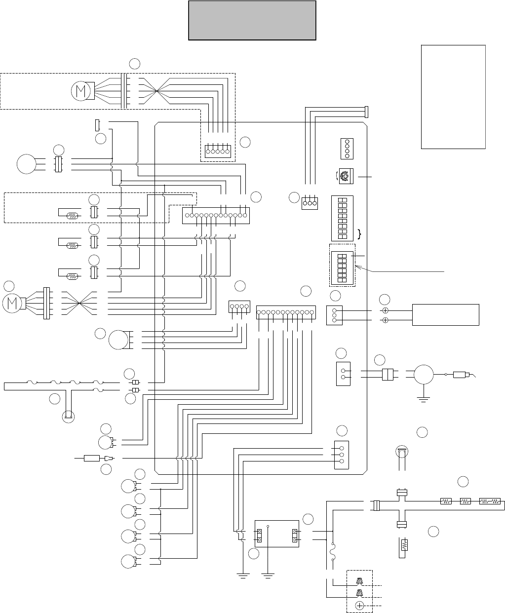
Wiring Diagram
305e/o, 305i, 505e/o, 505i
COLOR CODING
W :White
BK:Black
BR:Brown
R :Red
BL:Blue
Y :Yellow
P :Pink
O :Orange
G :Green
GY:Gray
1
3
BR
3
1
B
1
2
O
F
F
Dip SW1
3
8
7
6
5
4
F
5
W
W
B
1
BK
BK
MIN
MAX
MODULATING VALVE
CURRENT ADJUSTING
Gas pressure
F
4
W
W
W
P
W
W
OUTGOING WATER
THERMISTOR
HEAT EXCHANGER
THERMISTOR
Y
BR
O
R
W
BRROYW
BKRW
for REU-EZC
(Optional)
1
13
WATER FLOW
SENSOR
BK
F
2
Y
RR
Y
BK
QS
BY-PASS FLOW
CONTROL DEVICE
YBKR
FREEZE PROTECTION
OPTION
G
W
W
W
O
F
3
WW
O
P
BL
R
BR
Y
GY
WATER FLOW
CONTROL DEVICE
R
BL
BR
Y
GY
G
R
AIR TEMPERATURE
THERMISTOR
R
BL BR
Y
INDOOR MODEL ONLY
COMBUSTION FAN
FM
R
BK
Y
W
E
1
W
41
Y
BK
R
BY-PASS SERVO MODEL ONLY
1
1
THERMAL FUSES
R
R
OVERHEAT
SWITCH
H
2
H
1
MODULATING
SOLENOID VALVE
POV
H
3
P
P
H
4
Y
FLAME ROD
H
5
SV1
H
7
H
6
SV0
BL
BK
SV2
BK
P
Y
BK
MAIN SOLENOID VALVE
SOLENOID VALVE 1
SOLENOID VALVE 2
F
6
YBR
BLBKP
P
(CN2)
YP
R
12 1
SOLENOID VALVE 3
H
8
BR
BK
SV3
GY
C
1
IG
GY
GY
IGNITER
GND
GY
SURGE
PROTECTOR
3
1
BR
BL
G/Y
D
2
W
BK
1
3
GND
FUSE
(3A)
BKW
W
BLBL
D
4
ANTI-FROST HEATER
AC120VAC120V
HOT
NEUTRAL
HOT
NEUTRAL
GROUND
G/Y
D
1
GND
D
5
ANTI-FROST HEATER
BLBL
D
3
FROST SENSING
SWITCH
W
BL
REMOTE CONTROLLER
SPARK
ELECTRODE
5
4
Spare Parts Only
Gas type
1
2
3
O
F
F
Dip SW2
6
A
C
D
E
F
G
H
F
1
G
1
(CN3)
(CN4)
(CN1)
(CN12)
(CN5)
(CN7)
(CN9)
5
3
R
R
F
7
(W) (W)
On-Demand Gas Tankless Water Heater Service Manual
17

Wiring Diagram
705e/o (ASME),
705i (ASME)
A
3
1
W
3
1
B
1
2
O
F
F
Dip SW1
3
8
7
6
5
4
F
4
W
W
B
1
BK
BK
MIN
MAX
MODULATING VALVE
CURRENT ADJUSTING
Gas pressure
F
3
W
W
W
P
W
W
OUTGOING WATER
WATER THERMISTOR
HEAT EXCHANGER
WATER THERMISTOR
Y
BR
O
R
W
BRROYW
BKRW
for REU-EZC
(Optional)
1
13
WATER FLOW
SENSOR
BK
F
2
Y
RR
Y
BK
QS
BY-PASS FLOW
CONTROL DEVICE
YBKR
FREEZE PROTECTION
(OPTIONAL)
G
WW
P
BL
R
BR
Y
GY
W
ATER FLOW
CONTROL DEVICE
R
BL
BR
Y
GY
G
R
R
BL
BR
Y
COMBUSTION FAN
FM
R
BK
Y
W
E
1
W
4 1
Y
BK
R
1
1
MODULATING
SOLENOID VALVE
POV
H
2
O
O
H
7
Y
FLAME ROD
H
3
SV1
H
5
H
4
SV0
O
BK
SV2
BK
P
R
BK
MAIN SOLENOID VALVE
SOLENOID VALVE 1
(CENTER)
SOLENOID VALVE 2
(LEFT)
Y
Y
OBK
O
O
(CN2)
RP
W
12 1
SOLENOID VALVE 3
(RIGHT)
H
6
Y
BK
SV3
GY
C
1
IG
GY
GY
IGNITER
GND
GY
FUSE
(3A)
BK
W
AC120VAC120V
HOT
NEUTRAL
HOT
NEUTRAL
GROUND
GND
BK
REMOTE CONTROLLER
SPARK
ELECTRODE
5
4
Spare Parts Only
Gas type
1
2
3
O
F
F
Dip SW2
6
C
D
E
F
G
H
F
1
G
1
(CN3)
(CN4)
(CN1)
(CN12)
(CN5)
(CN7)
(CN9)
5
3
D
2
D
1
1
WBK
WBK
G/Y
SURGE
PROTECTOR
GND
R
W
RR
H
1
F
6
THERMAL FUSES
OVERHEAT
SWITCH
R
W
COLOR CODING
W :White
BK:Black
BR:Brown
R :Red
BL:Blue
Y :Yellow
P :Pink
O :Orange
G :Green
GY:Gray
BL BL
W
W
W
W
W
W
ANTI-FROST
HEATER
D
5
D
3
FROST SENSING
SWITCH
W
W
D
6
W
W
D
4
W
W
W
W
W
1
F
5
A
1
1
G/Y
On-Demand Gas Tankless Water Heater Service Manual
18
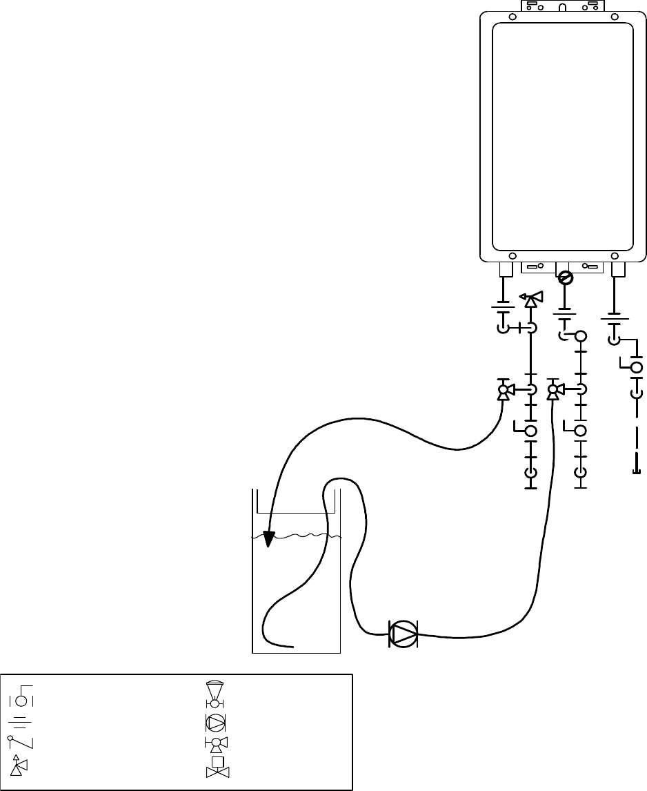
An “LC” or “00” error code indicates the unit is beginning to lime up and must be flushed. Failure to flush the
appliance will cause damage to the heat exchanger. Damage caused by lime build-up is not covered by the unit’s
warranty. After flushing, reset the LC fault code by turning off the power to the unit and turning the power back
on.
On-Demand
Gas Tankless
Water Heater
Pressure Relief Valve
3/4" Ball Valve
3/4" Union
Check Valve
S
Pressure Regulator
Circulating Pump
Solenoid Valve
Boiler Drain Valve
KEY
G
a
s
S
u
p
p
l
y
V1
V3
V2
V4
H1
H2
H3
Circulating Pump
5gallonpailof virgin,food
grade, white vinegar (or virgin,
food grade, citric acid).
C
o
ld
W
a
t
e
r
L
in
e
H
o
t
W
a
te
r
L
in
e
n
-
lin
e
F
ilt
e
r
I
1. Disconnect electrical power to the water heater.
2. Close the shutoff valves on both the hot water and cold
water lines (V3 and V4).
3. Connect pump outlet hose (H1) to the cold water line at
service valve V2.
4. Connect drain hose (H3) to service valve V1.
5. Pour approximately 4 gallons of virgin, food grade, white
vinegar or citric acid into pail.
6. Place the drain hose (H3) and the hose (H2) to the pump
inlet into the cleaning solution.
7. Open both service valves (V1 and V2) on the hot water and
cold water lines.
8. Operate the pump and allow the cleaning solution to
circulate through the water heater for at least 45 minutes.
9. Turn off the pump.
10. Rinse the cleaning solution from the water heater as follows:
a. Remove the free end of the drain hose (H3) from the pail.
b. Close
service valve, (V2), and open shutoff valve, (V4).
Do not open shutoff valve, (V3).
c. Allow water to flow through the water heater for 5 minutes
d. Close service valve, (V1), and open shutoff valve, (V3).
11. Disconnect all hoses.
12. With (V4) closed, remove the in-line
filter at the cold water inlet and clean
out any residue. Place filter back
into unit and open (V4).
13. Restore electrical power to the
water heater.
Flushing the Heat Exchanger
On-Demand Gas Tankless Water Heater Service Manual
19
IN-LINE CLEANING FILTER INSTRUCTIONS:
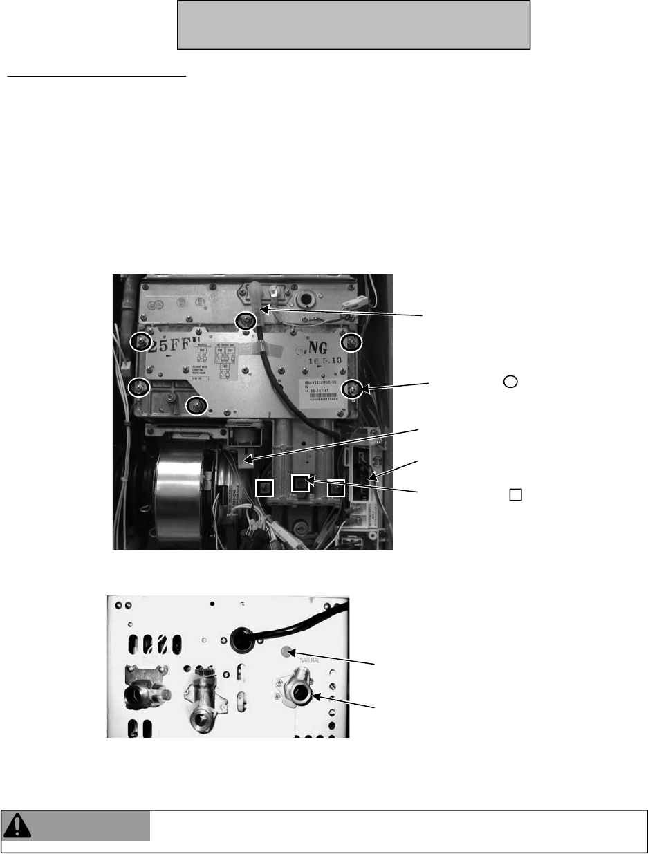
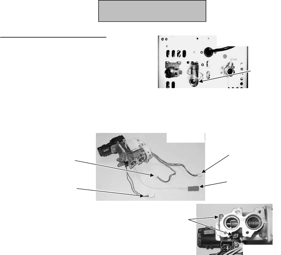
Component Replacement Instructions
Ignition line
Six screws
Wire harness connector
PC Board (dip switches)
Three screws
1. Turn off the gas supply.
2. Turn off the 120 V power supply.
3. Remove four screws securing the front panel. Remove front panel.
4. Pull out wire harness connector at the gas manifold assembly. See Figure 1.
5. Move aside the ignition line by pulling it out from the clear plastic tubing.
6. Remove the six screws that attach the gas manifold to the combustion chamber (part of the heat
exchanger assembly).
7. Remove the three screws that attach the gas manifold to the gas valve. Pull out the gas manifold.
Figure 1
8. Remove the four screws attaching the gas connection to the underneath side of the water heater.
See Figure 2.
Figure 2 Gas connection attached with 4 screws
Regulator screw access
9. Pull the gas connection down to disconnect it from the gas control assembly.
10. Pull out the gas control assembly. Remove the wire harness from the 4 solenoids.
11. Replace the O-ring (included in kit) where the assembly attaches to the gas connection. Make sure
the old O-ring is removed and discarded. Install the new gas control assembly.
WARNING
Failure to correctly assemble the components according to these instructions
could result in a gas leak or explosion.
305e/o, 305i, 505e/o, 505i
On-Demand Gas Tankless Water Heater Service Manual
20
Gas Control Assembly
Component Replacement Instructions
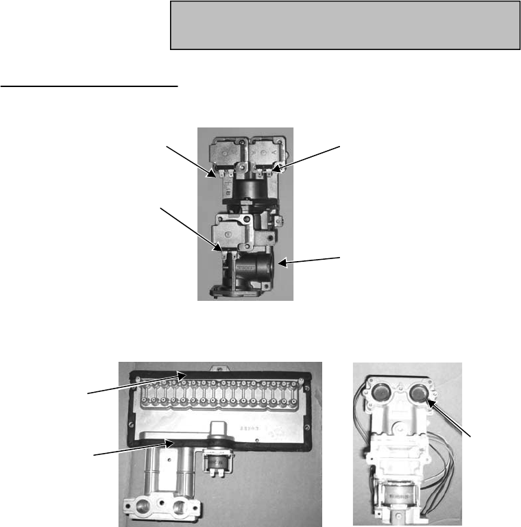
13. Install the gas manifold using 2 new packings (included in kit) between the manifold and the heat
exchanger. Replace the two circular gaskets (included in kit) in the gas valve (Figure 5).
14. Start the three screws that attach the gas manifold to the gas valve. Tighten the six screws that hold
the gas manifold to the combustion chamber. Finish tightening the three screws that hold the gas
manifold to the gas valve.
15. Attach wiring harness connector (black & brown wires) to the gas manifold.
16. Attach ignition line.
17. Perform the Gas Pressure Setting Procedure.
Figure 4
Figure 5
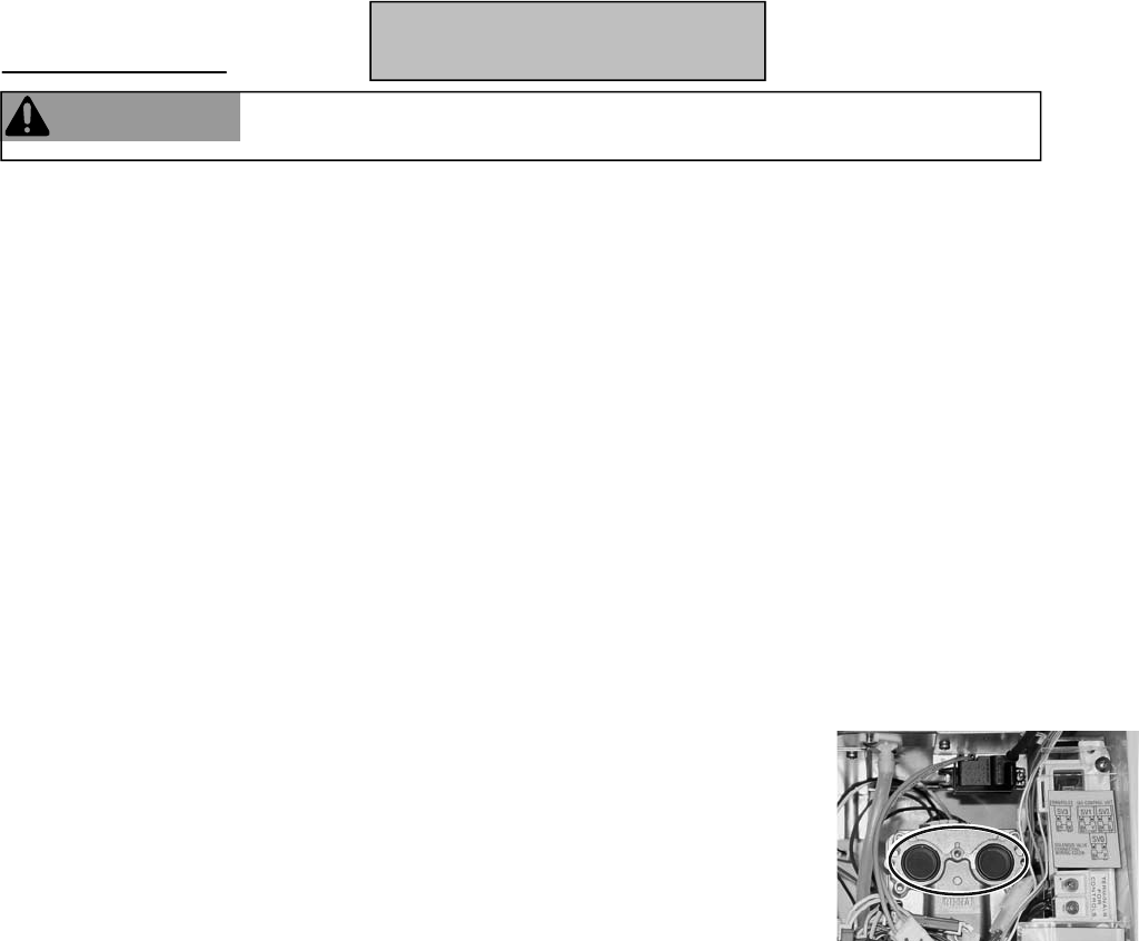
Circular gaskets (re-use)
in gas valve
wolley / kcalb 1VS eulb / kcalb 2VS
SV0 black / pink
POV pink / pink
(connector not shown)
Figure 3
12. Attach wire harness to the 4 solenoids as s
hown in Figure 3 below.
Upper packing
Lower packing
(U shaped)
Gas Control Assembly
On-Demand Gas Tankless Water Heater Service Manual
21
305e/o, 305i, 505e/o, 505i
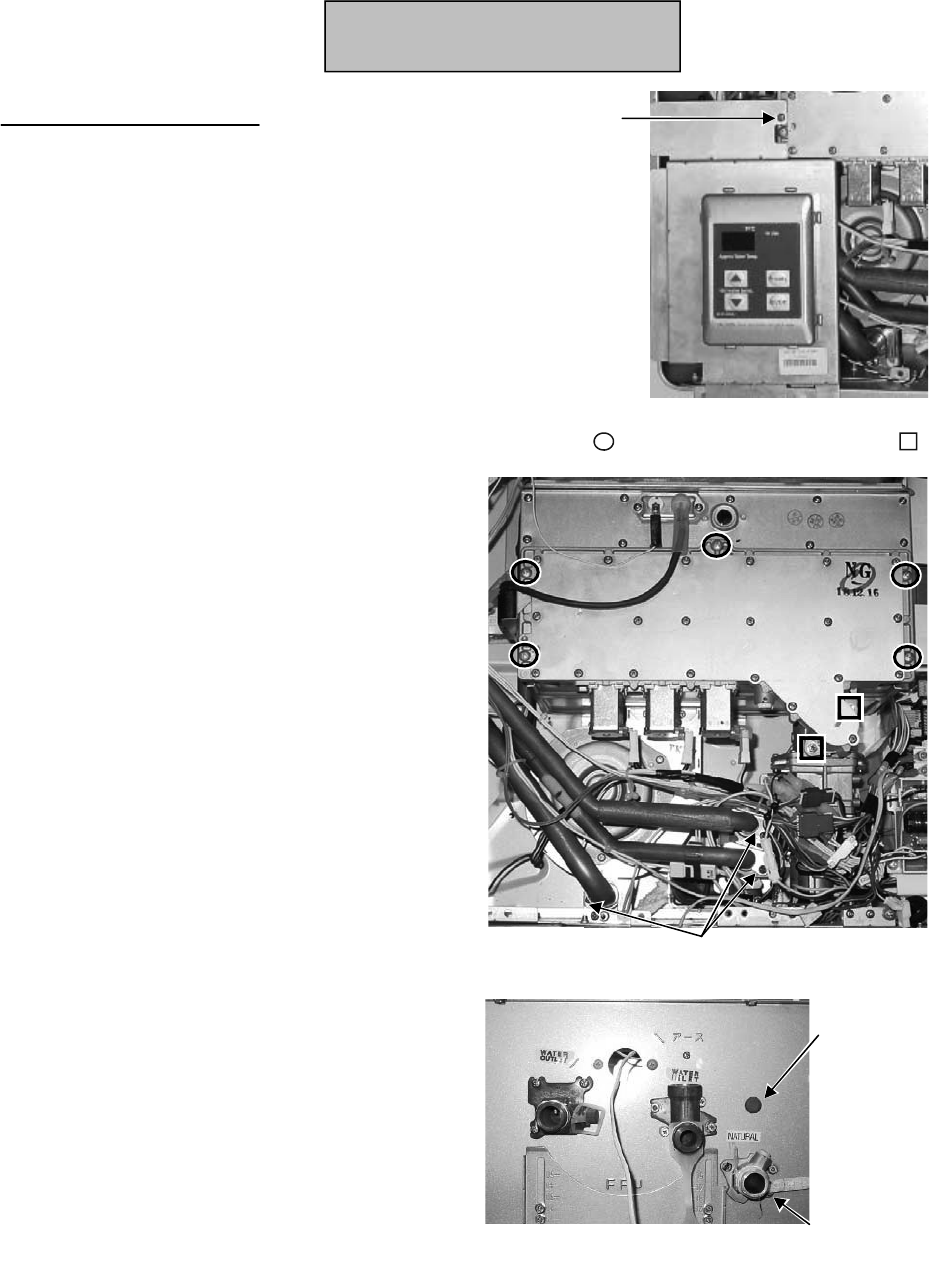
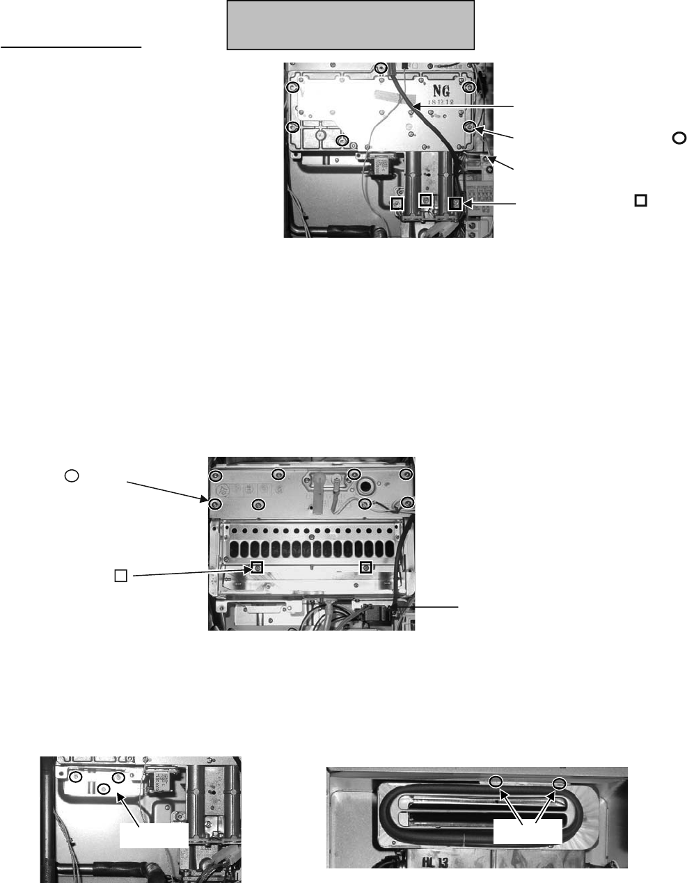
Component Replacement Instructions
1. Turn off the gas supply.
2. Turn off the 120 V power supply.
3. Remove four screws securing the front panel.
Remove front panel.
4. On indoor models, remove the bracket holding
the controller (1 screw). (Figure 6)
5. Move aside the ignition line by pulling it out from
the clear plastic tubing. (Figure 6)
6. Remove the 5 screws that attach the gas
manifold to the combustion chamber (part of the
heat exchanger assembly). (Figure 7)
7. Remove the 2 screws that attach the gas
manifold to the gas valve. These screws are
machine screws and must be used at these
locations. (Figure 7)
8. Pull out the gas manifold and remove the
connector at the ignitor at the left side of the gas
manifold.
9. Remove the 3 screws attaching the gas
connection to the underneath side of the water
heater. (Figure 8)
10.
Remove the screw attaching the gas valve to the
rear of the case.
11. Pull the gas connection down to disconnect it
from the gas control assembly.
Bracket screw
Figure 6
(indoor models)
Water line connections
Figure 7
5 screws
(gas manifold)
2 machine screws
(gas valve)
Figure 8
Regulator
screw
access
Gas connection
attached with 3 screws
On-Demand Gas Tankless Water Heater Service Manual
22
Gas Control Assembly
705e/o (ASME),
705i (ASME)
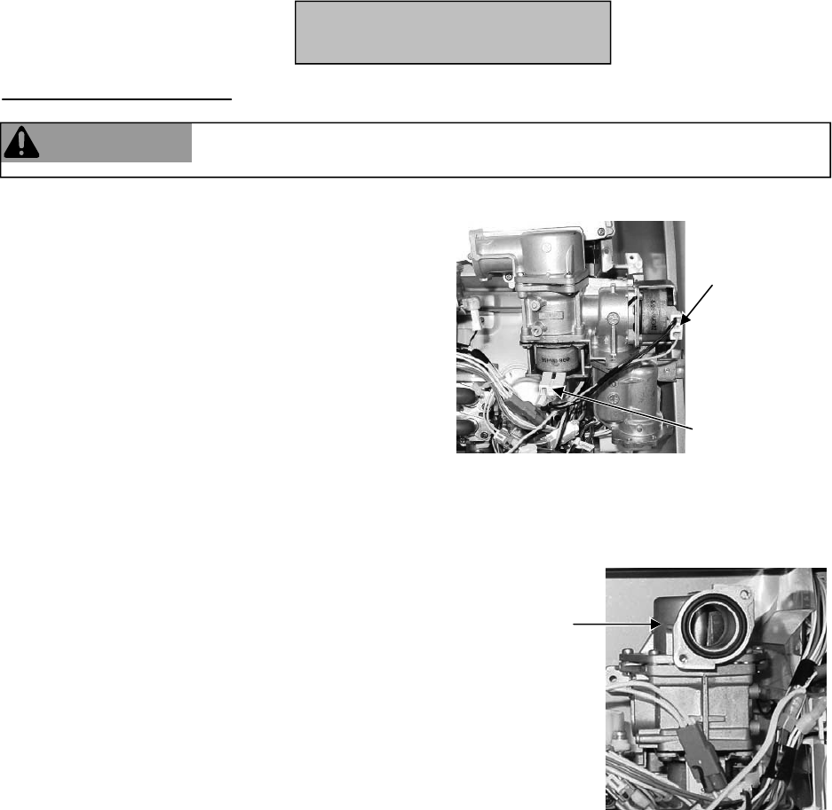
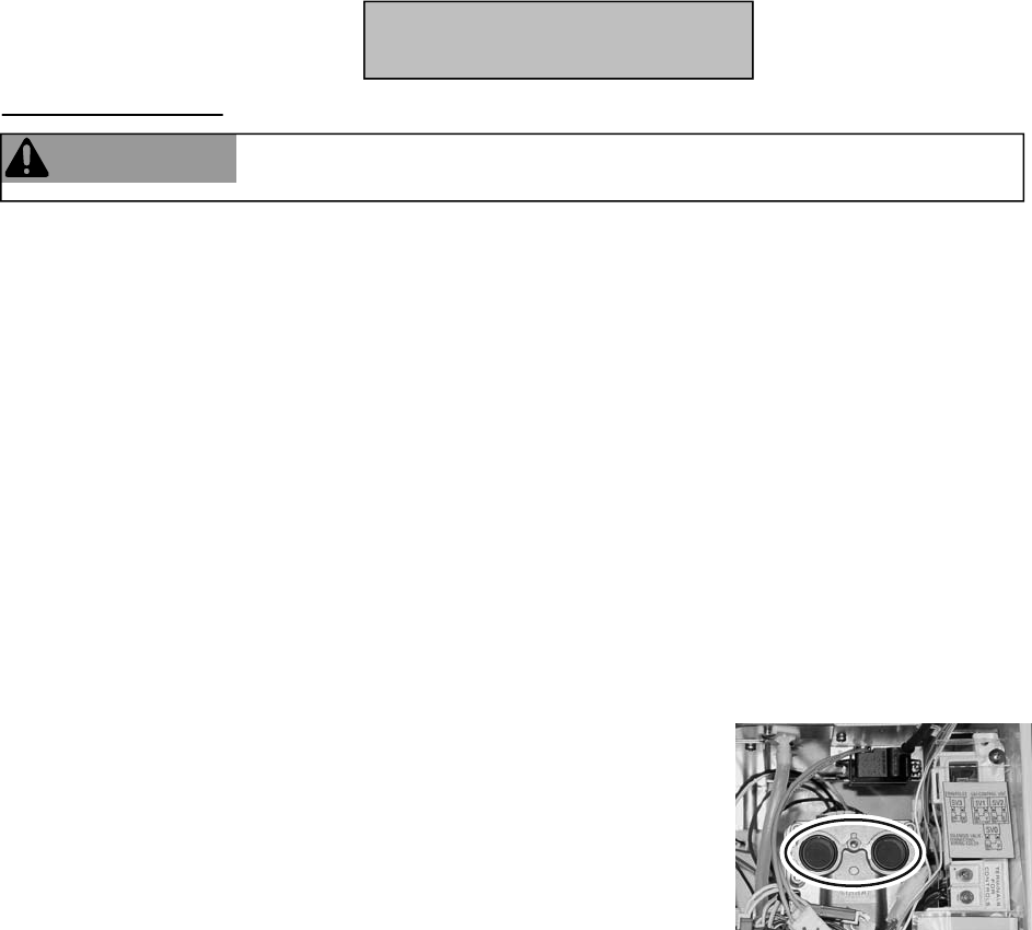
Component Replacement Instructions
Figure 10
black / orange
orange / orange
Figure 9
WARNING
Failure to correctly assemble the components according to these instructions
could result in a gas leak or explosion.
12. Pull out the gas control assembly. Remove the
wire harness from the 2 solenoids.
13. Install the gas valve and attach the wire harness
to the 2 solenoids. (Figure 9)
14. Install the gas connection with 3 screws.
15. Replace the circular gasket (included in kit) in the
gas valve. (Figure 10)
16. Start the 2 screws that attach the gas manifold to
the gas valve. Tighten the 5 screws that hold the
gas manifold to the combustion chamber. Finish
tightening the 2 screws that hold the gas manifold
to the gas valve.
17. Attach ignition line.
18. On indoor models, install the bracket with the
controller.
19. Perform the Gas Pressure Setting Procedure.
Gasket
Gas Control Assembly
On-Demand Gas Tankless Water Heater Service Manual
23
705e/o (ASME),
705i (ASME)
Component Replacement Instructions
305e/o, 505e/o
1. Turn off the gas supply.
2. Turn off the 120 V power supply.
3. Turn off the water supply.
4. Remove four screws securing the front panel. Remove front panel.
5. Disconnect wire harness at the fan assembly. Disconnect the air temperature thermistor (two white
wires) at the connection with the white and orange wires within the wire bundle.
6. Pull out the harness attached to the solenoid on the manifold to make room to pull out the fan as-
sembly.
7. Remove the two screws that attach the fan assembly to the bottom of the burner.
8. Pull out the fan assembly.
9. Install the fan assembly by inserting the tab on the fan assembly into the slot at the base of the heat
exchanger and attaching with two screws.
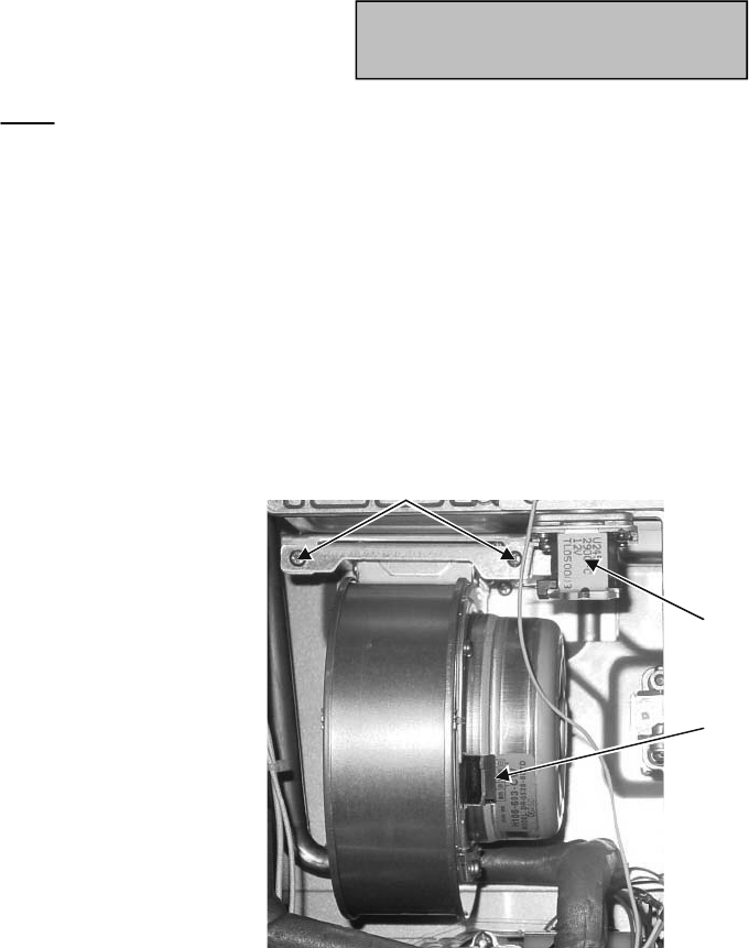
10. Attach the wire harness to the solenoid on the gas manifold (brown,
black wires).
11. Attach the wire harness to the fan assembly (white, yellow, black, red wires).
12. Attach the air temperature thermistor (white, white wires) to the wire harness.
13. Install front panel using 4 screws.
14. Turn on water supply, power supply, and gas supply.
Two screws
Wire harness connection
on the fan assembly
Solenoid on
the manifold
Figure 11
Fan
On-Demand Gas Tankless Water Heater Service Manual
24

Component Replacement Instructions
305i, 505i
1. Turn off the gas supply.
2. Turn off the 120 V power supply.
3. Turn off the water supply.
4. Remove four screws securing the front panel. Remove front panel.
5. Disconnect wire harness at the fan assembly. Disconnect the air temperature thermistor (two white
wires) at the connection with the white and orange wires within the wire bundle.
6. Pull out the harness attached to the solenoid on the manifold to make room to pull out the fan as-
sembly.
7. Loosen the ducting from the fan assembly by pinching open the metal clamp.
8. Remove the two screws that attach the fan assembly to the bottom of the burner.
9. Pull out the fan assembly.
10. Install the fan assembly by inserting the tab on the fan assembly into the slot at the base of the heat
exchanger and attaching with two screws.
11. Push ducting over fan assembly inlet and secure with metal clamp.
12. Attach the wire harness to the solenoid on the gas manifold (brown, black wires).
13. Attach the wire harness to the fan assembly (white, yellow, black, red wires).
14. Attach the air temperature thermistor (white, white wires) to the wire harness.
15. Install front panel using 4 screws.
16. Turn on water supply, power supply, and gas supply.
2 screws
Wire harness connection
on the fan assembly
Solenoid on the manifold
Wire harness bundle
(air temperature
thermistor connection to
orange / white wires)
Ducting and
metal clamp
Figure 12
Water outlet
connection
water flow servo
assembly
connection
Fan
On-Demand Gas Tankless Water Heater Service Manual
25

Component Replacement Instructions
705e/o (ASME),
705i (ASME)
1. Turn off the gas supply.
2. Turn off the 120 V power supply.
3. Turn off the water supply.
4. Remove four screws securing the front panel.
Remove front panel.
5. On indoor models, remove the bracket holding
the controller (1 screw). (Figure 13)
6. Disconnect the wire harness at the fan
assembly. (Figure 14)
7. Remove the three screws attaching the fan
motor to the fan casing. (Figure 14)
8. Pull out the fan motor.
9. Install the new fan motor and tighten with three
screws.
10. Attach the wire harness to the fan assembly
(white, yellow, black, red wires).
11. On indoor models, install the bracket with the
remote controller.
12. Install front panel using 4 screws.
13. Turn on water supply, power supply, and gas
supply.
3 screws
Figure 14
Wire Harness Connector
Bracket screw
Figure 13
(indoor m
odels)
Fan
On-Demand Gas Tankless Water Heater Service Manual
26
1. Turn off the gas supply.
2. Turn off the 120 V power supply.
3. Turn off the water supply.
4. Remove four screws securing the front panel.
Remove front panel.
5. Remove the plastic guard covering the front of the
PC board.
6. Remove the controller connections.
7. If a surge protector with terminals is installed, then
remove this board by removing two screws. This
board should be re-installed on the replacement PC
board.
8. Remove the two screws at the top and bottom of the
PC board.
9. Pull out the PC board, remove plastic cover, and
remove the connections.
10. Adjust dip switches on the new PC board.
11. Attach connections and plastic cover.
12. Insert PC board and attach with two screws.
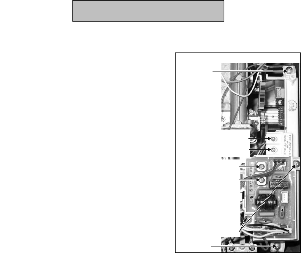
13. If a surge protector with terminals was installed on
the original PC board, remove it
and install it on the
new PC board. See Figure 15.
14. Attach connections for the remote controller.
15. Attach plastic guard.
16. Perform the Gas Pressure Setting Procedure.
Figure 15
Screw
Screw
Remote controller
terminals
(NOT for 120 V power)
If these 2 terminals are
present then this is a
surge protector board
with terminals to
connect freeze
protection solenoid
valves and should be
installed with the new
PC board.
Attached with 2 screws
Component Replacement Instructions
305e/o, 305i, 505e/o, 505i
Switches 1-8 (SW1): Configure the dip switches the
same as on the original PC board. If necessary,
refer to the Dip Switch section or to the Operation
and Installation Manual for more information on
these dip switches.
Switches 1-6 (SW2): Replacement PC boards have
an additional bank of 6 dip switches. Configure
according to the diagrams on the following page
based on your model and gas type.
PC Board
On-Demand Gas Tankless Water Heater Service Manuals
27

Propane (LPG) Natural Gas (NG)
SW2 setup for 505i
Switch No.
F
O
F
5
6
4
3
ON
1
2
Switch No.
F
O
F
5
6
4
3
ON
1
2
Switch No.
F
O
F
5
6
4
3
ON
1
2
Switch No.
F
O
F
5
6
4
3
ON
1
2
Component Replacement Instructions
Switch No.
F
O
F
5
6
4
3
ON
1
2
Switch No.
F
O
F
5
6
4
3
ON
1
2
Propane (LPG) Natural Gas (NG)
SW2 setup for 305i
Switch No.
F
O
F
5
6
4
3
ON
1
2
Switch No.
F
O
F
5
6
4
3
ON
1
2
Propane (LPG) Natural Gas (NG)
SW2 setup for 305e
Propane (LPG) Natural Gas (NG)
SW2 setup for 505e
PC Board
On-Demand Gas Tankless Water Heater Service Manual
28
305i, 305e, 505i, 505e
100/101 and 200/201 Series
Component Replacement Instructions
705e/o (ASME), 705i (ASME)
1. Turn off the gas supply.
2. Turn off the 120 V power supply.
3. Remove four screws securing the front panel.
Remove front panel.
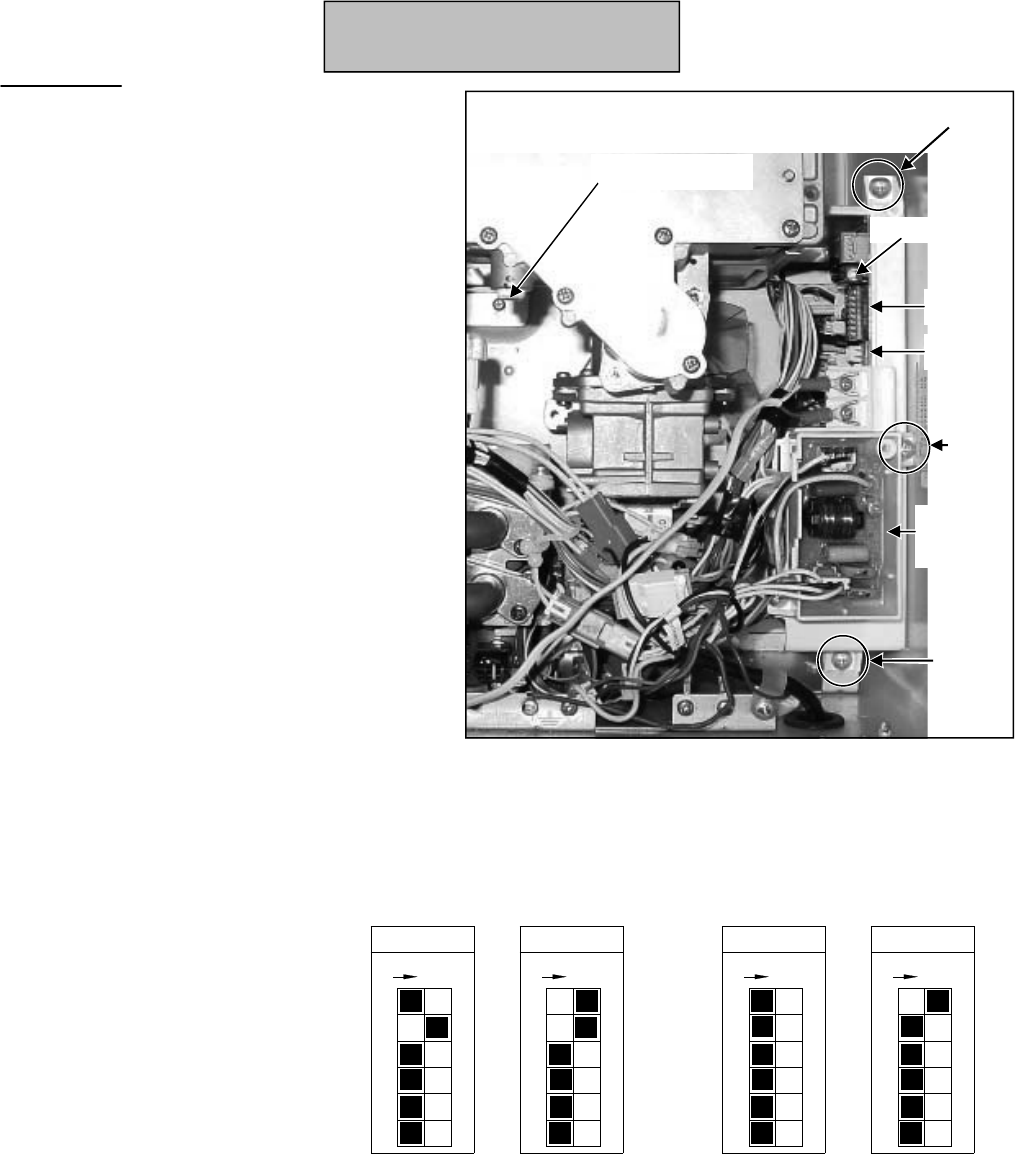
4. Remove the surge protector (2 screws)
5. Remove the 2 screws connecting the PC
board to the water heater casing.
6. Pull out the PC board and remove the
connections.
7. Adjust dip switches on the new PC board.
8. Attach connections and insert PC board.
Attach with 2 screws.
9. Attach the surge protector
with 2 screws.
10. Perform the Gas Pressure
Setting Procedure.
Figure 16
Screw
SW1
SW2
Burner test point
Potentiometer
Surge
protector
Screw
Switches 1-8 (SW1):
Configure the dip switches the same as on the
original PC board. If necessary, refer to the
Dip Switch section or to the Operation and
Installation Manual for more information on
these dip switches.
Switches 1-4 (SW2) or Switches 1-6 (SW2):
Configure according to the diagrams based on
your model and gas type.
Propane (LPG) Natural Gas (NG)
SW2 setup for 705i
Switch No.
F
O
F
5
6
4
3
ON
1
2
Switch No.
F
O
F
5
6
4
3
ON
1
2
Propane (LPG) Natural Gas (NG)
SW2 setup for 705e/o
Switch No.
F
O
F
5
6
4
3
ON
1
2
Switch No.
F
O
F
5
6
4
3
ON
1
2
PC Board
On-Demand Gas Tankless Water Heater Service Manual
29
Screw

Component Replacement Instructions
305e/o, 305i, 505e/o, 505i
1. Turn off the gas supply.
2. Turn off the 120 V power supply.
3. Turn off the water supply. Drain all water from the appliance.
4. Remove four screws securing the front panel. Remove front panel.
5. Remove 1 screw and bracket at the water flow assembly. The bracket can be left on the water line.
Pull out the water line. (Figure 17)
6. Remove the 4 screws attaching the water inlet to the underneath side of the water heater.
(Figure 18).
Remove the water flow assembly
Figure 17
Due to design changes, the new valve may appear different than the installed valve in
color, size, and in the number of wires in the harness connections.
NOTICE
Water inlet
Figure 18
1 screw and bracket
(water flow assembly)
Water Flow Control Assembly
On-Demand Gas Tankless Water Heater Service Manual
30
100/101 and 200/201 Series

Component Replacement Instructions
Assemble
A.water flow sensor harness (black/yellow/red wires)
B.water flow servo harness (red/blue/brown/yellow/gray or red/blue/brown/orange/yellow/gray wires)
C.heating element
7. Pull out the water flow servo assembly and disconnect the cable harnesses. (Figure 19)
8. Place the new water flow assembly inside the water heater and attach the cable harnesses.
9. Replace the O-ring on the water inlet (included in kit). Attach the water flow assembly through the
bottom of the compartment to the water inlet using 4 screws. The 2 shorter screws can be installed
first to connect the water flow assembly to the bottom of the compartment. Then install the 2 longer
screws through the water inlet.
10. Replace the O-ring on the water line (included in kit). Attach the water line to the
water flow
assembly with 1 screw and bracket.
11. Install the front panel using 4 screws.
12. Turn on the water supply, power supply, and gas supply.
13. Open a hot water tap and ensure there are no leaks at the water heater.
Figure 19
water flow servo connector
heating element
connector
water flow sensor
connector
Water Flow Control Assembly
On-Demand Gas Tankless Water Heater Service Manual
31
305e, 305i, 505e, 505i
100/101 and 200/201 Series
Component Replacement Instructions
505e/o, 505i
1. Turn off the gas supply.
2. Turn off the 120 V power supply.
3. Turn off the water supply. Drain all water from the appliance.
4. Remove four screws securing the front panel. Remove front panel.
Remove Fan Assembly (Figure 20)
5. Disconnect wire harness at the fan assembly. Disconnect the air temperature thermistor (two white wires) at
the connection with the white and orange wires within the wire bundle.
6. Pull out the harness attached to the solenoid on the manifold to make room to pull out the fan assembly.
7. Remove the 2 screws that attach the fan assembly to the bottom of the burner.
8. On indoor models, loosen the ducting from the fan assembly by pinching open the metal clamp.
9. Pull out the fan assembly.
10. Remove 2 screws and 2 brackets at the
water
flow servo assembly. The brackets can be
left on the water lines. Pull out the water
lines.
Remove the water flow assembly (Figure 21)
2 screws
Wire harness connection
on the fan assembly
Solenoid on the manifold
Wire harness bundle
(connection to orange /
white wires)
Ducting and
metal clamp
(indoor models
only)
Figure 20
Due to design changes, the new valve may appear different than the installed valve in
color, size, and in the number of wires in the harness connections.
NOTICE
Water flow
servo assembly
connections
Figure 21
Water Flow Control Assembly
On-Demand Gas Tankless Water Heater Service Manual
32
100/101 and 200/201 Series
Component Replacement Instructions
11. Remove the 4 screws attaching the water inlet to the
underneath side of the water heater.
a. water flow sensor harness (black/yellow/red wires)
b. bypass servo assembly harness (white/red/yellow/orange/brown wires)
c. water flow servo harness (red/blue/brown/yellow/gray or red/blue/brown/orange/yellow/gray wires)
d. heating element
12. Disconnect the cable harnesses (Figure 23):
Assemble
13. Pull out the water flow servo assembly and bypass servo assembly.
14. Remove 2 screws in order to separate the bypass servo assembly
from the water flow servo assembly. (Figure 24)
15. Replace the O-ring (included in kit) between the water flow servo assembly and the bypass servo assembly.
Attach the new water flow servo assembly to the bypass servo assembly with 2 screws.
16. Place in
side the water heater and attach the cable harnesses.
17. Replace the O-ring on the water inlet (included in kit). Attach the water flow assembly to the water inlet using
4 screws. The 2 shorter screws can be installed first to connect the water flow assembly to the bottom of the
compartment. Then install the 2 longer screws through the water inlet.
18. Replace the O-ring on the water lines (included in kit). Attach the two water lines to the bypass servo
assembly with 1 screw each.
19. Install the fan assembly by inserting the tab on the fan assembly into the slot at the base of the heat
exchanger and attaching with two screws.
20. On indoor models, push the ducting over the fan assembly inlet and secure with the metal pinch clamp.
21. Attach the wire harness to
the fan assembly (white, yellow, black, red wires).
22. Install the front panel using 4 screws.
23. Turn on the water supply, power supply, and gas supply.
24. Open a hot water tap and ensure there are no leaks at the water heater.
Figure 24
Water inlet
Figure 22
water flow servo
connector
heating element
connector
water flow sensor
connector
water flow servo
connector
Figure 23
Water Flow Control Assembly
On-Demand Gas Tankless Water Heater Service Manual
33
505e, 505i
100/101 and 200/201 Series

Component Replacement Instructions
705e/o (ASME), 705i (ASME)
1. Turn off the gas supply.
2. Turn off the 120 V power supply.
3. Turn off the water supply. Drain all water from the
appliance.
4. Remove four screws securing the front panel. Remove
front panel.
5. Remove 2 screws and 2 brackets at the water flow
servo assembly. Pull out the water lines. (Figure 25)
6. Remove the water flow sensor and the heating
element. (Figure 25)
7. Remove the 4 screws attaching the water inlet to the
underneath side of the water heater. (Figure 26)
8. Pull out the water flow servo assembly and bypass
servo assembly. Remove the wire harness from the
water servo valve. (Figure 27)
9. Remove 2 screws in order to separate the bypass
servo assembly from the water flow servo assembly.
(Figure 27)
10. Replace the O-ring (included in kit) be
tween the water
flow servo assembly and the bypass servo assembly.
Attach the new water flow servo assembly to the
bypass servo assembly with 2 screws.
11. Attach the wire harness to the water servo valve.
12. Place inside the water heater.
13. Attach the water flow assembly to the water inlet using
4 screws. The 2 shorter screws can be installed first to
connect the water flow assembly to the bottom of the
compartment. Install the 2 longer screws through the
water inlet.
14. Insert the heating element and attach the water flow
sensor.
15. Replace the O-ring on the water lines (included in kit).
Attach the two water lines to the bypass servo
assembly with 1 screw each.
16. Install the front panel using 4 screws.
17. Turn on the water supply, power su
pply, and gas
supply.
18. Open a hot water tap and ensure there are no leaks at
the water heater.
Figure 26
Water
inlet
Figure 25
Water
lines
Water flow
sensor
Heating
element
Figure 27
Bypass
servo
Water flow
servo
Screws (2)
Wire harness
Water Flow Control Assembly
On-Demand Gas Tankless Water Heater Service Manual
34

Component Replacement Instructions
305e
1. Turn off the gas supply.
2. Turn off the 120 V power supply.
3. Turn off the water supply. Drain all water
from the appliance.
4. Remove four screws securing the front panel.
Remove front panel.
Remove Fan Assembly (Figure 29)
5. Disconnect wire harness at the fan assembly.
Disconnect the air temperature thermistor
(two white wires) at the connection with the
white and orange wires within the wire
bundle.
6. Pull out the harness attached to the solenoid
on the manifold to make room to pull out the
fan assembly.
7. Remove the 2 screws that attach the fan
assembly to the bottom of the burner.
8. Pull out the fan assembly.
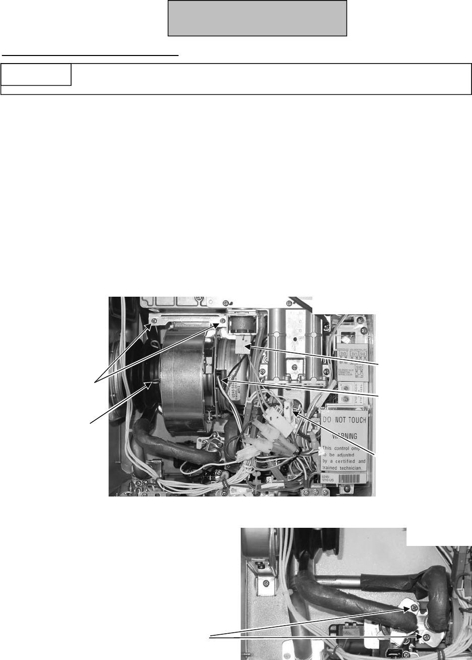
9. Remove 1 screw from the water outlet
bracket. Remove the bracket by rotating and
moving it up toward the bend in the tube
where the diameter is smaller.
10. Remove 1 screw and 1 b
racket at the water
flow servo assembly.
Figure 28
Fan Assembly
Gas Manifold
Burner cover
plate
PC Board
Gas Control
Valve
Figure 29
Wire
harness
connection
Solenoid
Figure 30
Water outlet
connection
Water flow servo
assembly connection
Disconnect Water Lines (Figure 30)
On-Demand Gas Tankless Water Heater Service Manual
35
Heat Exchanger
2 screws

Component Replacement Instructions
305e
Disconnect PC Board (Figure 31)
11. Remove 1 screw connecting the PC
Board to the heat exchanger assembly.
12. Remove the 6 screws that attach the gas
manifold to the combustion chamber
(part of the heat exchanger assembly).
13. Remove the 3 screws that attach the gas
manifold to the gas valve. These screws
are machine screws and must be used at
these locations.
14. Pull out the ignition line and remove the
gas manifold.
Remove Gas Manifold (Figure 31)
15. Remove the 8 screws attaching the burner cover plate to the combustion chamber. Move the cover plate to
the side. It is not necessary to disconnect the wire harness from the burner cover plate.
16. Remove the 2 screws attaching the burner to the heat exchanger. Pull out the burner.
17. Unscrew the ignition line connection. (Figure 32)
18. Remove the wire harness
attachments - sensors, heating elements, fusible link brackets. Ensure that the
small O-ring in the thermistor is removed.
19. Remove 3 screws behind the fan. (Figure 33)
20. Remove 2 screws above the exhaust. Pull assembly from the unit. (Figure 34)
Disconnect Wire Harness Attachments and Screws Holding the Heat Exchanger
Ignition line
6 screws (gas manifold)
PC Board screw
3 machine screws
(gas valve)
Figure 31
Ignition line
connection
8 screws
(burner cover plate)
2 screws (burner)
Figure 32
Remove Burner and Burner Cover Plate (Figure 32)
Figure 34
2 screws
Figure 33
3 screws
On-Demand Gas Tankless Water Heater Service Manual
36
Heat Exchanger
Component Replacement Instructions
305e
21. Install the largest O-ring (included in kit) over the water outlet tube and the two smaller O-rings (included in kit)
over the bypass servo tubes. (Figure 30)
22. Remove any other attached items and install on the new heat exchanger.
23. Install the new heat exchanger using 2 screws above the exhaust and 3 screws behind the fan. (Figures 33, 34)
Connect Pressure Tube and Wire Harness Attachments
24. Connect wire harness attachments.
25. Connect the pressure tube.
26. Attach the ignition line connection with 1 screw.
Install Burner and Burner Cover Plate (Figure 32)
27. Replace the combustion chamber packing (included in kit) removing any residue from old packing. Insert the
burner and place the burner cover plate into position. Attach the burner cover plate first with 8 screws and
then
attach the burner with 2 screws.
Install Gas Manifold and Connect PC Board
28. Make sure that the two black packings (Figure 35) are intact on the gas control
assembly. Attach the gas manifold with 3 machine screws at the gas control
assembly. Replace the lower and upper packings (included in kit) for the
manifold plate removing any residue.
29. Attach the gas manifold with 6 screws at heat exchanger.
30. Attach the ignition line at the burner cover plate.
31. Attach the PC Board to the heat exchanger with 1 screw.
Connect Water Lines (Figure 30)
32. Attach the water outlet line and bracket with 1 screw.
33. Attach the line to the water flow servo assembly with 1 screw and 1 bracket.
Install Fan Assembly (Figure 29)
34. Install the fan assembly by inserting the tab on the fan assembly into the slot at the base of the heat
exchanger and attaching with
two screws.
35. Attach the wire harness to the solenoid on the gas manifold (brown, black wires).
36. Attach the wire harness to the fan assembly (white, yellow, black, red wires).
37. Attach the air temperature thermistor (white, white wires) to the wire harness.
38. Install the front panel using 4 screws.
39. Turn on the water supply, power supply, and gas supply.
40. Check for gas leaks.
Figure 35
WARNING
Failure to correctly assemble the components according to these instructions
could result in a gas leak or explosion.
Installation
On-Demand Gas Tankless Water Heater Service Manual
37
Heat Exchanger

Component Replacement Instructions
505e/o
1. Turn off the gas supply.
2. Turn off the 120 V power supply.
3. Turn off the water supply. Drain all water
from the appliance.
4. Remove four screws securing the front panel.
Remove front panel.
Remove Fan Assembly (Figure 37)
5. Disconnect wire harness at the fan assembly.
Disconnect the air temperature thermistor
(two white wires) at the connection with the
white and orange wires within the wire
bundle.
6. Pull out the harness attached to the solenoid
on the manifold to make room to pull out the
fan assembly.
7. Remove the 2 screws that attach the fan
assembly to the bottom of the burner.
8. Pull out the fan assembly.
9. Remove 1 screw from the water outlet
bracket. Remove the bracket by rotating and
moving it up toward the bend in the tube
where the diameter is smaller.
10. Remove 2 screws and 2
brackets at the
bypass servo assembly.
Fan Assembly
Gas Manifold
Burner cover
plate
PC Board
Gas Control
Valve
Figure 36
Wire
harness
connection
Solenoid
Figure 37
Figure 38
Water outlet
connection
Bypass servo assembly
connections
Disconnect Water Lines (Figure 38)
On-Demand Gas Tankless Water Heater Service Manual
38
Heat Exchanger
2 screws
Component Replacement Instructions
Disconnect PC Board (Figure 39)
11. Remove 1 screw connecting the PC
Board to the heat exchanger
assembly.
12. Remove the 6 screws that attach the
gas manifold to the combustion
chamber (part of the heat exchanger
assembly).
13. Remove the 3 screws that attach the
gas manifold to the gas valve. These
screws are machine screws and must
be used at these locations.
Remove Gas Manifold (Figure 39)
14. Pull out the ignition line and remove the gas manifold.
15. Remove the 8 screws attaching the burner cover plate to the combustion chamber. Move the cover
plate to the side. It is not necessary to disconnect the wire harness from the burner cover plate.
16. Remove the 2 screws attaching the burner to the heat exchanger. Pull out the burner.
17. Unscrew the ignition line connection. (Figure 40)
18. Remove the wire harness attachments - sensors,
heating elements, fusible link brackets. Ensure
that the small O-ring in the thermistor is removed.
19. Remove 3 screws behind the fan. (Figure 41)
Disconnect Wire Harness Attachments and Screws Holding the Heat Exchanger
Ignition line
6 screws (gas manifold)
PC Board screw
(gas valve)
Figure 39
Ignition line
connection
8 screws
(burner cover plate)
2 screws (burner)
Figure 40
Remove Burner and Burner Cover Plate (Figure 40)
Figure 42
2 screws
Figure 41
3 screws
On-Demand Gas Tankless Water Heater Service Manual
39
Heat Exchanger
505e/o
3 machine screws
Component Replacement Instructions
20. Remove 2 screws above the exhaust. Pull assembly from the unit. (Figure 42)
21. Install the largest O-ring (included in kit) over the water outlet tube and the two smaller O-rings
(included in kit) over the bypass servo tubes. (Figure 38)
22. Remove any other attached items and install on the new heat exchanger.
Connect Pressure Tube and Wire Harness Attachments
23. Install the new heat exchanger using 2 screws above the exhaust and 3 screws behind the fan.
(Figures 41, 42)
Install Burner and Burner Cover Plate (Figure 40)
24. Connect wire harness attachments.
25. Connect the pressure tube. Attach the ignition line connection with 1 screw.
Install Gas Manifold and Connect PC Board
26. Replace the combustion chamber packing (included in kit) removing
any residue from old packing. Insert the burner and place the burner
cover p
late into position. Attach the burner cover plate first with 8
screws and then attach the burner with 2 screws.
27. Make sure that the two black packings (Figure 43) are intact on the
gas control assembly. Attach the gas manifold with 3 machine screws
at the gas control assembly. Replace the lower and upper packings
(included in kit) for the manifold plate removing any residue.
Connect Water Lines (Figure 38)
28. Attach the gas manifold with 6 screws at heat exchanger.
29. Attach the ignition line at the burner cover plate.
Install Fan Assembly (Figure 37)
30. Attach the PC Board to the heat exchanger with 1 screw.
31. Attach the water outlet line and bracket with 1 screw.
32. Attach the two lines to the bypass servo assembly with 1 screw and 1 bracket for each line.
33. Install the fan assembly by inserting the tab on the fan assembly int
o the slot at the base of the heat
exchanger and attaching with two screws.
34. Attach the wire harness to the solenoid on the gas manifold (brown, black wires).
35. Attach the wire harness to the fan assembly (white, yellow, black, red wires).
Figure 43
WARNING
Failure to correctly assemble the components according to these instructions
could result in a gas leak or explosion.
Installation
On-Demand Gas Tankless Water Heater Service Manual
40
Heat Exchanger
505e/o

Component Replacement Instructions
305i
1. Turn off the gas supply.
2. Turn off the 120 V power supply.
3. Turn off the water supply. Drain all water
from the appliance.
4. Remove four screws securing the front panel.
Remove front panel.
2 screws
Wire harness connection
on the fan assembly
Solenoid on the manifold
Wire harness bundle
(air temperature
thermistor connection to
orange / white wires)
Ducting and
metal clamp
Remove Fan Assembly (Figure 45)
5. Disconnect wire harness at the fan assembly.
Disconnect the air temperature thermistor
(two white wires) at the connection with the
white and orange wires within the wire
bundle.
6. Pull out the harness attached to the solenoid
on the manifold to make room to pull out the
fan assembly.
7. Remove the 2 screws that attach the fan
assembly to the bottom of the burner.
8. Loosen the ducting
from the fan assembly by
pinching open the metal clamp.
9. Pull out the fan assembly.
10. Remove 1 screw from the water outlet bracket. Remove the bracket by rotating and moving it up
toward the bend in the tube where the diameter is smaller.
11. Remove the screw and bracket at the water flow servo assembly.
12. Remove 1 screw connecting the PC Board to the heat exchanger assembly.
Disconnect Water Lines and PC Board (Figure 45)
Fan Assembly
Gas Manifold
Burner cover
plate
PC Board
Gas Control
Valve
Figure 44
Figure 45
Water outlet
connection
water flow servo
assembly
connection
PC board screw
On-Demand Gas Tankless Water Heater Service Manual
41
Heat Exchanger
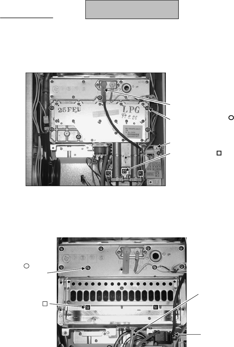
Component Replacement Instructions
Ignition line
6 screws (gas manifold)
PC Board screw
3 machine screws
(gas valve)
13. Remove the 6 screws that attach the gas manifold to the combustion chamber (part of the heat exchanger
assembly).
14. Remove the 3 screws that attach the gas manifold to the gas valve. These screws are machine screws and
must be used at these locations.
15. Pull out the ignition line and remove the gas manifold.
Remove Gas Manifold (Figure 46)
16. Remove the 8 screws attaching the burner cover plate to the combustion chamber. Move the cover plate to
the side. It is not necessary to disconnect the wire harness from the burner cover plate.
17. Remove the 2 screws attaching the burner to the heat exchanger. Pull out the burner.
18. Disconnect the pressure tube from the heat exchanger and unscrew the ignition line connection.
Pressure tube
Ignition line
connection
8 screws
(burner cover plate)
2 screws (burner)
Figure 46
Figure 47
Remove Burner and Burner Cover Plate (Figure 47)
On-Demand Gas Tankless Water Heater Service Manual
42
Heat Exchanger
305i

Component Replacement Instructions
19. Remove the wire harness attachments - sensors, heating elements, fusible link brackets. Ensure
that the small O-ring in the thermistor is removed.
Disconnect Wire Harness Attachments
Remove Heat Exchanger and Air Intake/Exhaust
20. Remove 8 screws connecting the assembly to the water heater casing assembly. (Figures 48, 49)
Separate the Heat Exchanger from the Air Intake/Exhaust
21. Pull out the assembly. Remove 3 brackets on the side and back holding the fusible link.
22. Remove the 9 screws at the cover plate over the air intake passage. (Figure 50)
23. Remove the 4 screws attaching the heat exchanger to the air intake/exhaust assembly. (Figure 51)
24. Pull apart the heat exchanger and air intake/exhaust assembly. (Figure 52)
25. Remove 4 screws attaching the bracket on top of the heat exchanger. Pull off the bracket. (Figure 53)
4 screws
(bracket)
9 screws
(cover plate)
Figure 50
4 screws
Figure 51
Figure 52
Figure 53
At right and left upper corners of water heater
Near fan assembly location
2 screws 2 screws
Figure 49
1 screw
3 screws
Figure 48
WARNING
Failure to correctly assemble the components according to these instructions
could result in a gas leak or explosion.
Heat Exchanger
On-Demand Gas Tankless Water Heater Service Manual
43
305i
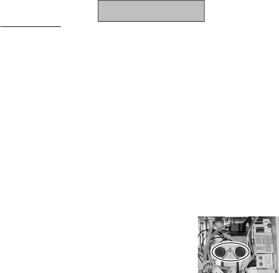
Component Replacement Instructions
26. Install the O-ring (included in kit) over the water outlet tube and the O-ring (included in kit) over the water flow
servo tube. (Figure 45)
27. Install the bracket over the replacement heat exchanger. Push evenly on both sides of the bracket. Attach
with four screws. (Figure 54)
Combine the Heat Exchanger and the Air Intake/Exhaust Assembly
28. Push the heat exchanger into the air intake/exhaust assembly. Attach with four screws. (Figure 51)
29. Attach the cover plate over the air intake passage with 9 screws. (Figure 51)
Install Heat Exchanger and Air Intake/Exhaust Assembly (Figures 48, 49)
30. Attach the fusible link to the back (2 brackets) and side (1 bracket). Slide the assembly into the casing
assembly and attach with 8 screws starting at the top of the water heater.
Connect Pressure Tube and Wire Harness Attachments
31. Connect wire harness attachments.
32. Connect the pressure tube. Attach the ignition line connection with 1 screw. (Figure 47)
Install Burner and Burner Cover Plate (Figure 47)
33. Replace the combustion chamber packing (included in kit) removing any residue from old packing. Insert the
burner and place the burner cover plate into position. Attach the burner cover plate first with 8 screws and
then attach the burner with 2 screws.
Install Gas Manifold and Connect PC Board
34. Make sure that the two black packings (Figure 54) are intact on the
gas control assembly. Attach the gas manifold with 3 machine
screws at the gas control assembly. Replace the lower and upper
packings (included in kit) for the manifold plate removing any residue.
35. Attach the gas manifold with 6 screws at heat exchanger.
36. Attach the ignition line at the burner cov
er plate.
Connect Water Lines (Figure 45)
37. Attach the PC Board to the heat exchanger with 1 screw.
38. Attach the water outlet line and bracket with 1 screw.
39. Attach the two lines to the bypass servo assembly with 1 screw and 1 bracket for each line.
Install Fan Assembly (Figure 45)
40. Install the fan assembly by inserting the tab on the fan assembly into the slot at the base of the heat
exchanger and attaching with two screws.
41. Push the ducting over the fan assembly exit and secure with the metal pinch clamp.
42. Attach the wire harness to the solenoid on the gas manifold (brown, black wires).
43. Attach the wire harness to the fan assembly (white, yellow, black, red wires).
44. Attach the air temperature thermistor (white, white wires) to the wire harness.
45. Install the front panel using 4
screws.
46. Turn on the water supply, power supply, and gas supply.
47. Check for gas leaks.
Figure 54
Install Packings and Bracket
Heat Exchanger
On-Demand Gas Tankless Water Heater Service Manual
44
305i
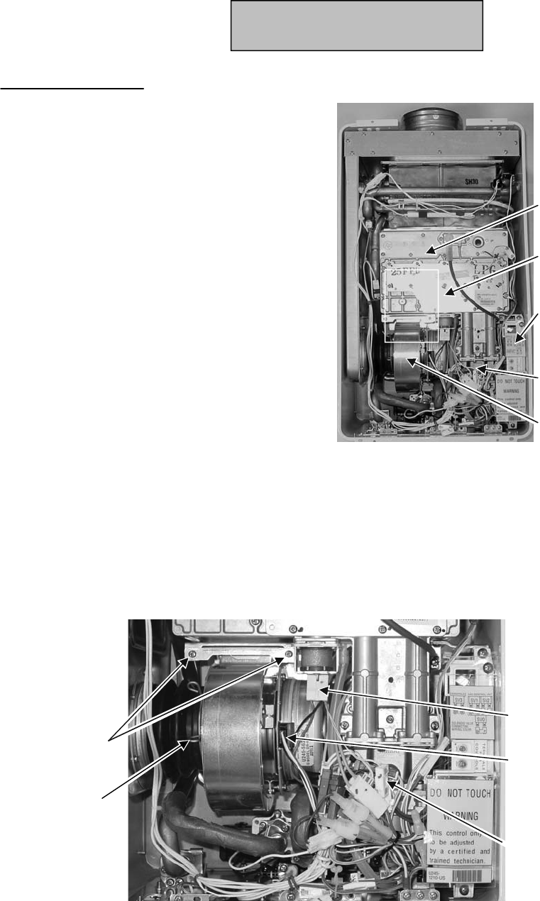
Component Replacement Instructions
1. Turn off the gas supply.
2. Turn off the 120 V power supply.
3. Turn off the water supply. Drain all water
from the appliance.
4. Remove four screws securing the front panel.
Remove front panel.
Remove Fan Assembly (Figure 56)
5. Disconnect wire harness at the fan assembly.
Disconnect the air temperature thermistor
(two white wires) at the connection with the
white and orange wires within the wire
bundle.
6. Pull out the harness attached to the solenoid
on the manifold to make room to pull out the
fan assembly.
7. Remove the 2 screws that attach the fan
assembly to the bottom of the burner.
8. Loosen the ducting from the fan assembly by
pinching open the metal clamp.
9. Pull out the fan assembly.
Fan Assembly
Gas Manifold
Burner cover
plate
PC Board
Gas Control
Valve
Figure 55
2 screws
Wire harness connection
on the fan assembly
Solenoid on the manifold
Wire harness bundle
(air temperature
thermistor connection to
orange / white wires)
Ducting and
metal clamp
Figure 56
Heat Exchanger
On-Demand Gas Tankless Water Heater Service Manual
45
505i

Component Replacement Instructions
Disconnect PC Board (Figure 58)
10. Remove 1 screw from the water outlet bracket. Remove the bracket by rotating and moving it up
toward the bend in the tube where the diameter is smaller.
11. Remove 2 screws and 2 brackets at the bypass servo assembly.
Disconnect Water Lines (Figure 57)
12. Remove 1 screw connecting the PC Board to the heat exchanger assembly.
Remove Gas Manifold (Figure 58)
13. Remove the 6 screws that attach the gas manifold to the combustion chamber (part of the heat
exchanger assembly).
14. Remove the 3 screws that attach the gas manifold to the gas valve. These screws are machine
screws and must be used at these locations.
15. Pull out the ignition line and remove the gas manifold.
Figure 57
Water outlet
connection
Bypass servo
assembly
connections
Ignition line
6 screws (gas manifold)
PC Board
screw
3 machine screws
(gas valve)
Figure 58
Heat Exchanger
On-Demand Gas Tankless Water Heater Service Manual
46
505i
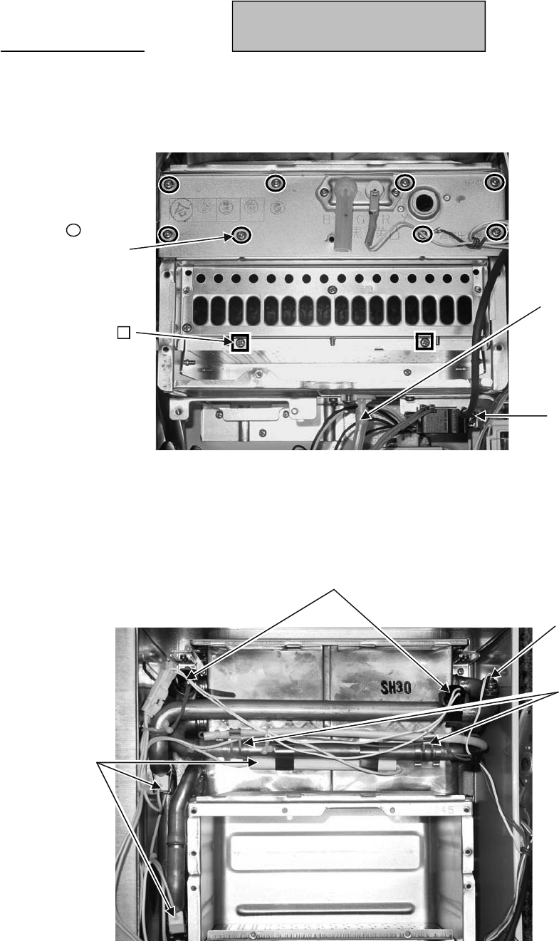
Component Replacement Instructions
505i
Remove Burner and Burner Cover Plate (Figure 59)
16. Remove the 8 screws attaching the burner cover plate to the combustion chamber. Move the cover
plate to the side. It is not necessary to disconnect the wire harness from the burner cover plate.
17. Remove the 2 screws attaching the burner to the heat exchanger. Pull out the burner.
Disconnect Gas Line and Wire Harness Attachments
18. Disconnect the pressure tube from the heat exchanger and unscrew the ignition line connection.
(Figure 59)
19. Remove the wire harness attachments - sensors, heating elements, fusible link brackets. Ensure
that the small O-ring in the thermistor is removed. (Figure 60)
Pressure tube
Ignition line
connection
8 screws
(burner cover plate)
2 screws (burner)
Figure 59
Brackets for
fusible link
Sensors
Heating
elements
Figure 60
Thermistor
Heat Exchanger
On-Demand Gas Tankless Water Heater Service Manual
47

Component Replacement Instructions
505i
Remove Heat Exchanger and Air Intake/Exhaust
20. Remove 8 screws connecting the assembly to the water heater casing assembly. (Figures 61, 62)
Separate the Heat Exchanger from the Air Intake/Exhaust
21. Pull out the assembly. Remove 3 brackets on the side and back holding the fusible link.
22. Remove the 9 screws at the cover plate over the air intake passage. (Figure 63)
23. Remove the 4 screws attaching the heat exchanger to the air intake/exhaust assembly. (Figure 64)
24. Pull apart the heat exchanger and air intake/exhaust assembly. (Figure 65)
25. Remove 4 screws attaching the bracket on top of the heat exchanger. Pull off the bracket. (Figure 66)
At right and left upper corners of water heater Near fan assembly location
4 screws
(bracket)
9 screws
(cover plate)
Figure 63
4 screws
Figure 64
Figure 65
Figure 66
26. Install the largest O-ring (included in kit) over the water outlet tube and the two smaller O-rings (included in kit)
over the bypass servo tubes. (Figure 57)
27. Install the bracket over the replacement heat exchanger. Push evenly on both sides of the bracket. Attach
with four screws. (Figure 66)
2 screws 2 screws
Figure 62
1 screw
3 screws
Figure 61
WARNING
Failure to correctly assemble the components according to these instructions
could result in a gas leak or explosion.
Install Packings and Bracket
Heat Exchanger
On-Demand Gas Tankless Water Heater Service Manual
48
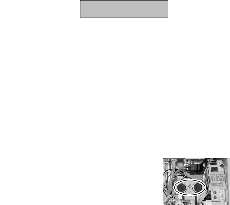
Component Replacement Instructions
Combine the Heat Exchanger and the Air Intake/Exhaust
28. Push the heat exchanger into the air intake/exhaust assembly. Attach with four screws. (Figure 64)
29. Attach the cover plate over the air intake passage with 9 screws. (Figure 63)
Install Heat Exchanger and Air Intake/Exhaust Assembly (Figures 61, 62)
30. Attach the fusible link to the back (2 brackets) and side (1 bracket). Slide the assembly into the
casing assembly and attach with 8 screws starting at the top of the water heater.
Connect Pressure Tube and Wire Harness Attachments
31. Connect wire harness attachments. (Figure 60)
32. Connect the pressure tube.
33. Attach the ignition line connection with 1 screw. (Figure 59)
Install Burner and Burner Cover Plate (Figure 59)
34. Replace the combustion chamber packing (included in kit) removing any residue from old packing. Insert the
burner and place the bur
ner cover plate into position. Attach the burner cover plate first with 8 screws and
then attach the burner with 2 screws.
Install Gas Manifold and Connect PC Board
35. Make sure that the two black packings (Figure 67) are intact on the
gas control assembly. Attach the gas manifold with 3 machine
screws at the gas control assembly. Replace the lower and upper
packings (included in kit) for the manifold plate removing any residue.
36. Attach the gas manifold with 6 screws at heat exchanger.
37. Attach the ignition line at the burner cover plate.
Connect Water Lines (Figure 57)
38. Attach the PC Board to the heat exchanger with 1 screw.
39. Attach the water outlet line and bracket with 1 screw.
40. Attach the two lines to the bypass servo assembly with 1 screw and 1 bracket for each line.
Install Fan Assembly (Figure 56)
41. Install the fan assembly by inserting the tab on the fan assembly into the slot at the base of the heat
exchanger and attaching with two screws.
42. Push the ducting over the fan assembly exit and secure with the metal pinch clamp.
43. Attach the wire harness to the solenoid on the gas manifold (brown, black wires).
44. Attach the wire harness to the fan assembly (white, yellow, black, red wires).
45. Attach the air temperature thermistor (white, white wires) to the wire harness.
46. Install the front panel using 4 screws.
47. Turn on the water supply, power supply, and gas supply.
48. Check for gas leaks.
Figure 67
Heat Exchanger
On-Demand Gas Tankless Water Heater Service Manual
49
505i

Component Replacement Instructions
705e/o (ASME)
1. Turn off the gas supply.
2. Turn off the 120 V power supply.
3. Turn off the water supply. Drain all water
from the appliance.
4. Remove four screws securing the front
panel. Remove front panel.
5. Disconnect wire harness at the fan
assembly, the electrical connections to
the 3 solenoid valves, and the ignition
line.
6. Remove 3 screws and brackets securing
the water line connections. (Figure 68)
7. Remove the 5 screws that attach the gas
manifold to the combustion chamber
(part of the heat exchanger assembly).
(Figure 68)
8. Remove the 2 screws that attach the gas
manifold to the gas valve. These screws
are machine screws and must be used at
these locations. (Figure 68)
9. Pull out the gas manifold and remove the
connector at the ignitor at the left side of
the gas manifold.
10. Remove
the 9 screws attaching the
burner cover plate to the combustion
chamber. (Figure 69)
11. Remove the 2 screws attaching the
burner to the heat exchanger. Pull out
the burner. (Figure 69)
12. Remove the wire harness attachments -
sensors, heating elements, fusible link
brackets. Ensure that the small O-ring at
the thermistor is removed.
13. Remove the 4 screws connecting the
heat exchanger to the casing. (Figure 70)
14. Pull out the assembly. Remove the
brackets on the side and back holding
the fusible link. Slide off the fusible link.
9 screws
(burner cover plate)
2 screws
(burner)
Figure 69
Water line connections
Figure 68
5 screws
(gas manifold)
2 machine screws
(gas valve)
Figure 70
Bottom screws
Top screws
Heat Exchanger
On-Demand Gas Tankless Water Heater Service Manual
50

Component Replacement Instructions
15. Remove the fan assembly (4 screws) and
install it on the new heat exchanger. (Figure 71)
16. Remove the flue outlet (6 screws) and install it
on the new heat exchanger. (Figure 72)
17. Install the largest O-ring (included in kit) over
the water outlet tube and the two smaller O-
rings (included in kit) over the water inlet
tubes. (Figure 71)
18. Slide the fusible link between the water outlet
and inlet tubes and onto the new heat
exchanger. (Figure 71)
19. Attach brackets at the back and side holding
the fusible link.
20. Install the 4 screws at the top and bottom of
the heat exchanger to the casing. (Figure 70)
21. Insert the burner and place the burner cover
plate into position. Attach the burner cover
plate first with 9 screws and then attach the
burner with 2 screws. (Figure 69)
22. Replace
the electrode gasket. (Figure 73)
23. Make sure that the black gasket (Figure 74) is
intact on the gas control assembly. Replace
the lower and upper gaskets (included in kit)
for the manifold plate removing any residue.
(Figure 75)
24. Attach the electrical connector to the ignitor
on the manifold and attach the gas manifold
with 2 machine screws at the gas control
assembly. (Figure 68)
25. Attach the gas manifold with 5 screws at heat
exchanger. (Figure 68)
26. Connect wire harness attachments.
27. Attach the ignition line at the burner cover
plate.
28. Attach the 3 electrical connectors to the
solenoid valves.
29. Attach the wire harness to the fan assembly
(white, yellow, black, red wires).
30. Attach the brackets to the water line
connections. (Figure 68)
31. Install the front panel using 4 screws. Turn
on
the water supply, power supply, and gas
supply. Check for gas leaks.
Figure 74
Gasket
Figure 75
Gaskets
Figure 73
Electrode
Gasket
Figure 71
4 locations
Water
outlet tube
tubes
Figure 72
Heat Exchanger
On-Demand Gas Tankless Water Heater Service Manual
51
Water inlet
705e/o (ASME)

Component Replacement Instructions
705i (ASME)
1. Turn off the gas supply.
2. Turn off the 120 V power supply.
3. Turn off the water supply. Drain all water
from the appliance.
4. Remove four screws securing the front
panel. Remove front panel.
5. Remove the bracket holding the
controller (1 screw). (Figure 76)
6. Disconnect wire harness at the fan
assembly, the electrical connections to
the 3 solenoid valves, and the ignition
line.
7. Remove 3 screws and brackets securing
the water line connections. (Figure 77)
8. Remove the 5 screws that attach the gas
manifold to the combustion chamber
(part of the heat exchanger assembly).
(Figure 77)
9. Remove the 2 screws that attach the gas
manifold to the gas valve. These screws
are machine screws and must be used at
these locations. (Figure 77)
10. Pull out the gas manifold and re
move the
connector at the ignitor at the left side of
the gas manifold.
11. Remove the 9 screws attaching the
burner cover plate to the combustion
chamber. (Figure 78)
12. Remove the 2 screws attaching the
burner to the heat exchanger. Pull out
the burner. (Figure 78)
13. Remove the wire harness attachments -
sensors, heating elements, fusible link
brackets. Ensure that the small O-ring at
the thermistor is removed.
Bracket screw
Figure 76
9 screws
(burner cover plate)
2 screws
(burner)
Figure 78
Water line connections
Figure 77
5 screws
(gas manifold)
2 machine screws
(gas valve)
Heat Exchanger
On-Demand Gas Tankless Water Heater Service Manual
52

Component Replacement Instructions
14. Remove the 3 screws at the seal plate at
the top of the water heater. Remove the
seal plate and gasket. (Figure 79)
15. Remove flue outlet vent (4 screws).
(Figure 80)
16. Remove the 4 screws connecting the
heat exchanger to the back of the casing.
(Figure 81)
17. Pull out the assembly. (It is hooked on
brackets in the casing.) Remove the
brackets on the side and back holding
the fusible link. Slide off the fusible link.
18. Remove the fan assembly (4 screws)
and install it on the new heat exchanger.
(Figure 82)
19. Install the largest O-ring (included in kit)
over the water outlet tube and the two
smaller O-rings (included in kit) over the
water inlet tubes. (Figure 82)
20. Slide the fusible link between the water
outlet and inlet tubes and onto the new
heat exch
anger. (Figure 82)
21. Attach brackets at the back and side
holding the fusible link. Install the heat
exchanger hooking it on the brackets in
the back.
22. Install the 4 screws at the top and bottom
of the heat exchanger to the back of the
casing. (Figure 81)
23. Install the flue outlet vent (4 screws) and
seal plate (3 screws) and gasket at the
top of the water heater. (Figures 79 and 80)
80 erugiF 79 erugiF
Figure 82
Figure 81
Top left screw Top right screw
Bottom screws
4 locations
Heat Exchanger
On-Demand Gas Tankless Water Heater Service Manual
53
Water outlet tube
Water inlet tubes
705i (ASME)
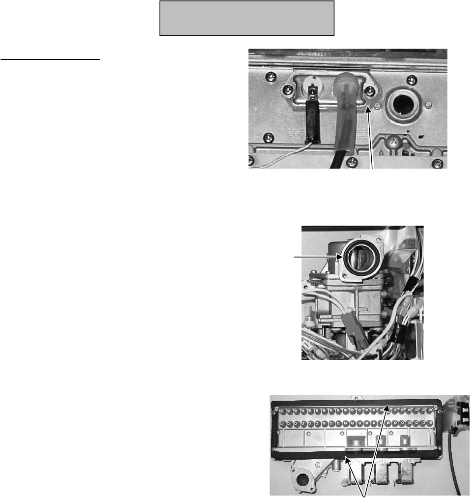
Component Replacement Instructions
24. Insert the burner and place the burner
cover plate into position. Attach the
burner cover plate first with 9 screws and
then attach the burner with 2 screws.
(Figure 78)
25. Replace the electrode gasket. (Figure 83)
26. Make sure that the black gasket (Figure 84)
is intact on the gas control assembly.
Replace the lower and upper gaskets
(included in kit) for the manifold plate
removing any residue. (Figure 85)
27. Attach the electrical connector to the
ignitor on the manifold and attach the gas
manifold with 2 machine screws at the
gas control assembly. (Figure 77)
28. Attach the gas manifold with 5 screws at
heat exchanger. (Figure 77)
29. Connect wire harness attachments.
30. Attach the ignition line at the burner
cover plate.
31. Attach the 3 electrical connectors to the
solenoid valves.
32. Attach the wire
harness to the fan
assembly (white, yellow, black, red
wires).
33. Attach the brackets to the water line
connections. (Figure 77)
34. Install the front panel using 4 screws.
35. Turn on the water supply, power supply,
and gas supply.
36. Check for gas leaks.
Figure 84
Gasket
Figure 85
Gaskets
Figure 83 Electrode Gasket
Heat Exchanger
On-Demand Gas Tankless Water Heater Service Manual
54
705i (ASME)
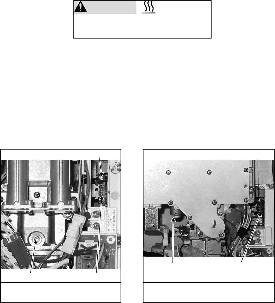
Gas Pressure Setting Procedure
1. Remove the front panel (four screws).
2. Calibrate the low fire and high fire settings as follows:
A. Remove the allen head plug and attach the manometer to the burner test point located
on the gas control (Figure 86 or 87).
CAUTION
Do not touch the areas at or near the heat
exchanger or combustion chamber. These areas
become very hot and could cause burns.
100/101 and 200/201 Series
Models 305e/o, 305i, 505e/o, 505i
Figure 86 Potentiometer (POT)
Burner test point Dip switches (SW1)
Potentiometer (POT)
Burner test point Dip switches (SW1)
Figure 87
On-Demand Gas Tankless Water Heater Service Manual
55
Models 705e/o (ASME), 705i (ASME)
100/101 and 200/201 Series
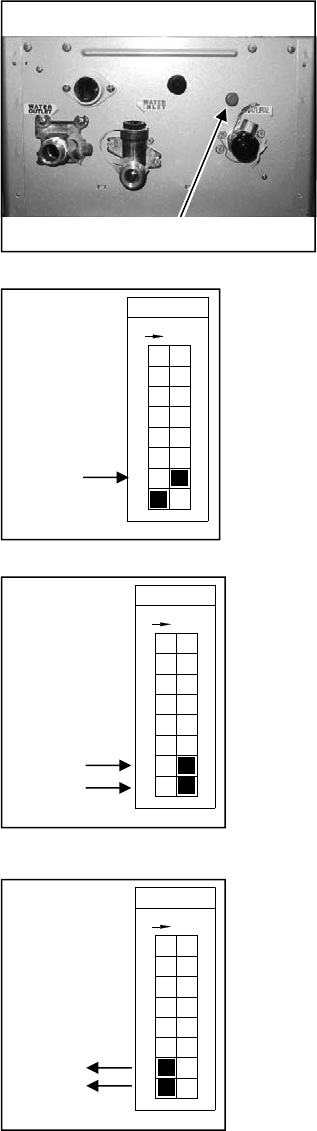
Figure 89
Forced Low
Switch No.
F
O
F
8
5
7
6
4
3
ON
1
2
Figure 90
Forced High
Switch No.
F
O
F
8
5
7
6
4
3
ON
1
2
Figure 91
Normal
Switch No.
F
O
F
8
5
7
6
4
3
ON
1
2
Figure 88
Access plug
B. Turn on the gas supply.
C. Turn on the power supply.
D. Flow water through the water heater at the
maximum flow rate obtainable. (At least 3
gallons per minute is recommended.)
E. Move No. 7 dip switch of the SW1 bank to the
ON position to calibrate “Forced Low”
combustion. (Figure 89)
F. Check the burner test point pressure.
G. Remove the rubber access plug (Figure 88) and
adjust the regulator screw on the modulating
valve to obtain the correct low fire manifold
pressure. Refer to the data plate on the unit.
Install rubber access plug.
H. Move No. 7 and No. 8 dip switches of the SW1
bank to the ON position to calibrate “Forced
High” combustion. (Figure 90)
I. Check the burner test point pressure.
J. Adjust the high pressure Potentiometer (POT)
(Figure 86 or 87) on the PC Board to obtain the
correct high fire manifold pressure. Refer to the
data plate on the unit.
K. Move No. 7 and No. 8 back to the OFF position
to return the appliance to “Normal” combustion.
(Figure 91)
L. Close hot water taps.
M. Turn off gas supply and 120 V power supply.
N. Remove manometer and re-install allen head
plug.
O. Turn on the gas supply and 120 V power
supply.
P. Operate the unit and check for gas leaks.
3. Install the front panel using four screws.
Gas Pressure Setting Procedure
On-Demand Gas Tankless Water Heater Service Manual
56
Manifold Gas Pressure Settings
100/101 and 200/201 Series
Altitude High Fire Low Fire High Fire Low Fire
305e/o
2.9 0.56 4.2 0.88
505e/o
3.3 0.56 5.1 0.88
705e/o (ASME)
2.8 0.65 3.8 0.80
305i
2.7 0.52 4.4 0.92
505i
3.3 0.52 5.0 0.92
705i (ASME)
3.0 0.67 3.7 0.83
less than 10200 ft
(3109 m)
Natural Gas Propane Gas
On-Demand Gas Tankless Water Heater Service Manual
57
(Inch - W.C.)
(Inch - W.C.)
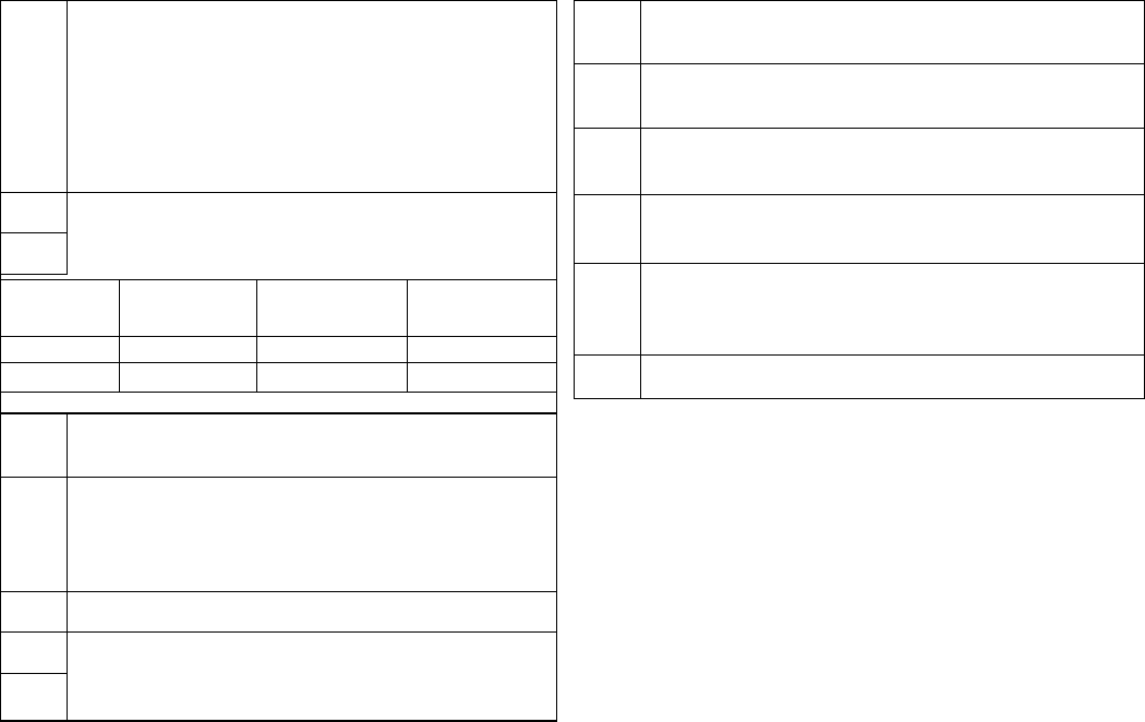
0-2000 ft
(0-610 m)
2001-5200 ft
(610-1585 m)
5201-7700 ft
(1585-2347 m)
7701-10200 ft
(2347-3109 m)
#2: OFF #2: OFF #2: ON #2: ON
#3: OFF #3: ON #3: OFF #3: ON
Dip Switch Settings
100/101 and 200/201 Series
SW1 Bank
SW2 Bank (present on replacement PC boards only)
OFF - 305e, 305i, 505e, 505i,
705e/o (ASME), 705i (ASME)
OFF - 505e/o, 505i, 705e/o (ASME), 705i (ASME)
ON - 305e/o, 305i
OFF - 305e, 305i, 505e, 505i, 705e/o (ASME),
705i (ASME)
1
OFF - Propane Gas
ON - Natural Gas
2
OFF - Outdoor model
ON - Indoor model
3
4
5
6 OFF position
1
OFF - “Long Flue”
ON - “Short Flue” and Outdoor Models
2
Settings dependent on altitude
3
4
OFF - if using standard controller
5
OFF - 120ºF default temperature without a
controller
ON - 140ºF default temperature without a
controller
6 OFF position
7
OFF position - Used for low fire and high fire
settings. Refer to the gas pressure setting
procedure.
8
“Long flue” is defined as:
0 elbows and length is greater than 21 ft
1 elbow and length is greater than 15 ft
2 elbows and length is greater than 9 ft
On-Demand Gas Tankless Water Heater Service Manual
58
Notes
On-Demand Gas Tankless Water Heater Service Manual
59
• 500 Tennessee Waltz Parkway • Ashland, TN 37015 •
